
Estimated Study Time: 14 minutes
What is a Single line diagram (SLD)?
We usually depict the electrical distribution system by a graphic representation called a single line diagram (SLD). A single line can show all or part of a system. It is very versatile and comprehensive because it can depict very simple DC circuits, or a very complicated three-phase system.
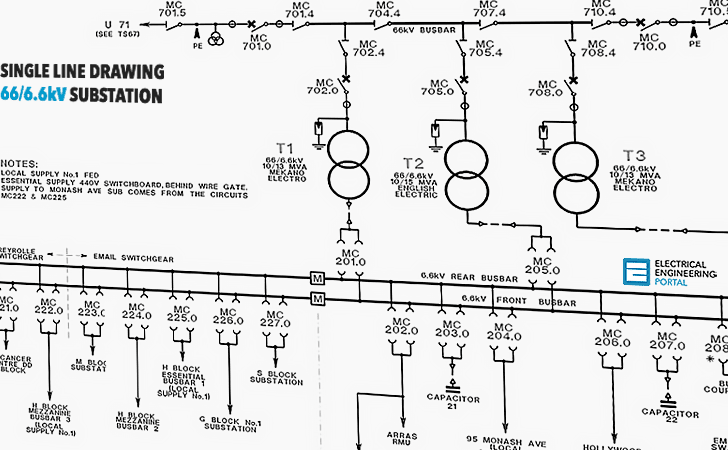 Learn To Interpret Single Line Diagram - SLD (on photo: An example of 66/6.6kV power substation single line diagram)
A single line diagram is a simplified schematic of a multi-line power distribution system, which may include three-phase, three-phase with neutral, single-phase with neutral, or direct current with two lines. One-line diagrams utilize a single line to represent the many components of a distribution system as seen in a schematic or wiring diagram.
This simplification enhances readability and consolidates numerous circuits on a single plane, aiming to provide a comprehensive picture of the installation and electrical distribution of the unit in issue.
A single line diagram is a schematic representation that illustrates the framework of electrical networks, including automated systems that serve different components of a unit, depicting their interconnections and the associated equipment.
Practices in SLDs – simple annotation
- Multiple conductors are depicted by just one line.
- This line specifies the quantity of conductors arranged in parallel.
- This depiction is predominantly utilized in three-phase distribution, which is the most prevalent and standard form of distribution. A single line diagram can encompass various forms of distribution on a single page, including three-phase, single-phase, and direct current (DC).
- The symbols for multi-pole electrical equipment are identical to those utilized in other diagram types, namely in the representation of a single pole.
- Single line diagrams represent the “electrical connections” among the various elements/components of an installation, rather than their physical placement connections.
- Single line diagrams consolidate and deliver extensive details
The single-wire system is used when a schematic depiction of a distribution system “principle” is desired. This example only uses a one-line “sketch” to illustrate how different distribution networks work, thus the symbols aren’t fully formed.
Electrical symbols used in single line diagrams
We use universally accepted electrical symbols to represent the different electrical components and their relationship within a circuit or system. To interpret SLDs you first need to be familiar with the electrical symbols. This chart shows the most frequently used symbols.
| Individual electrical symbols | ||
| Symbol | Identification | Explanation |
| Transformer | Represents a variety of transformers from liquid filled to dry types. Additional information is normally printed next to symbol indicating winding connections, primary /secondary voltages and KVA or MVA ratings. | |
| Removable or drawout circuit breaker | Normally represents a MV drawout circuit breaker 5kV and above. | |
| Future removable or drawout circuit breaker position | Represents a structure equipped to accept circuit breaker in the future, commonly known as provisions. | |
| Non-drawout circuit breaker | Represents a fixed mounted low voltage circuit breaker. | |
| Removable or drawout circuit breaker | Represents a drawout low voltage circuit breaker. | |
| Disconnect switch | Represents a switch in low or medium/high voltage applications (open position shown) | |
| Fuse | Represents low voltage and power fuses. | |
| Bus duct | Represents low and medium/high voltage bus duct. | |
| Current transformer | Represents current transformers mounted in assembled equipment. A ratio of 4000A to 5A shown. | |
| | Potential or voltage transformer | Represents potential transformers usually mounted in assembled equipment. A ratio of 480V to 120V shown. |
| | Ground (earth) | Represents a grounding (earthing) point |
| | Battery | Represents a battery in an equipment package |
| | Motor | Represents a motor and is also shown with an “M” inside the circle. Additional motor information is commonly printed next to symbol, such as horsepower, RPM and voltage. |
| | Normally open (NO) contact | Can represent a single contact or single pole switch in the open position for motor control |
| | Normally closed (NC) contact | Can represent a single contact or single pole switch in the closed position for motor control |
| | Indicating light | The letter inside circle indicates the color. The color red is indicated. |
| | Overload relay | Protects a motor should an overload condition develop. |
| Capacitor | Represents a variety of capacitors. | |
| Ammeter | A letter is usually shown to designate the meter type (A = ammeter, V = voltmeter, etc.) | |
| Instantaneous overcurrent protective relay | The device number designates the relay type (50 = instantaneous overcurrent, 59 = overvoltage, 86 = lockout, etc.) | |
| Emergency generator | The symbol is frequently shown in conjuction with a transfer switch. | |
| Fused disconnect switch | The symbol is a combination of a fuse and disconnect switch with the switch in the open position. | |
| Low voltage motor control | The symbol is a combination of a normally open contact (switch), overload relay, motor and disconnect device. | |
| Medium voltage motor starter | The symbol is a combination of a drawout fuse, normally open contact (switch) and motor. | |
| | Meter center | A series of circle symbols representing meters usually mounted in a common enclosure. |
| | Load center or panelboard | One circuit breaker representing a main device and other circuit breakers representing feeder circuits usually in a common enclosure. |
 | Transfer switch | • Circuit breaker type transfer switch • Non-circuit breaker type transfer switch |
| Current transformer with connected ammeter | The instrument connected could be a different instrument or several different instruments identified by the letter. | |
| Protective relays connected to current transformer | Device numbers indicate types of relays connected, such as: • 67 – Directional overcurrent • 51 – Time overcurrent | |
Simple electrical circuit
Now, that you are familiar with electrical symbol, let’s look at how they are used in interpreting single line diagrams. Below is a simple electrical circuit.

You can tell by the symbols that this single line diagram has three resistors and a battery. The electricity flows from the negative side of the battery through the resistors to the positive side of the battery.
Industrial single line diagram
Now, lets go through a industrial single line diagram. When interpreting a single line diagram, you should always start at the top where the highest voltage is and work your way down to the lowest voltage. This helps to keep the voltages and their paths straight.
To explain this easier, we have divided the single line into three sections.
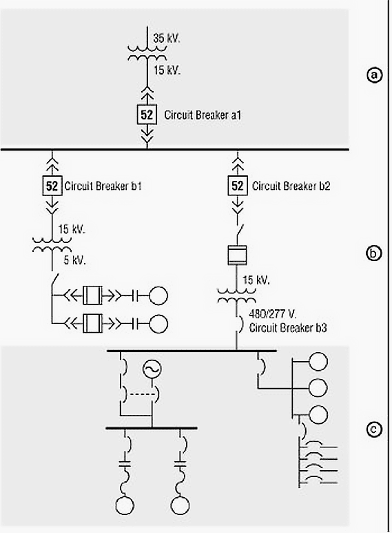
Area A:
Starting at the top, you will notice that a transformer is feeding power to the whole system. The transformer steps the voltage down from 35kV to 15kV, as indicated by the numbers next to the transformer symbol. Once the voltage has been stepped down, a drawout circuit breaker (a1) is encountered.
Do you recognize the drawout circuit breaker symbol?
You can assume this circuit breaker can handle 15kV, since it is attached to the 15kV side of the transformer, and nothing different is indicated on the single line diagram. Following the drawout circuit breaker (a1) from the transformer, it is attached to a heavier, horizontal line.
This horizontal line represents an electrical bus, which is a means used to get electricity to other areas or circuits.
Area B:
You will notice that two more drawout circuit breakers (b1 and b2) are attached to the bus and feed other circuits, which are at 15kV, since there has been no indication of voltage change in the system. Attached to the drawout circuit breaker (b1), a step-down transformer is used to take the voltage in that area of the system from 15kV down to 5kV.
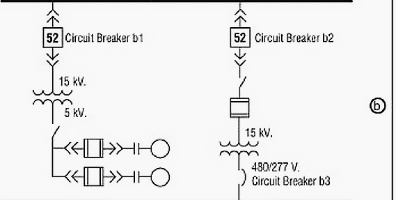
On the 5kV side of this transformer, a disconnect switch is shown. The disconnect is used to connect or isolate the equipment below it from the transformer. The equipment below the disconnect is at 5kV, since nothing indicates the contrary.
Do you recognize the equipment attached to the lower side of the disconnect switch as being two medium-voltage motor starters?
A number of starters could be connected depending upon the particular system requirements. Now locate the second drawout circuit breaker (b2). This circuit breaker is attached to a fused disconnect switch and it is connected to a step-down transformer. Notice that all the equipment below the transformer is now considered low voltage equipment, because the voltage has been stepped down to a level of 600 volts or lower.
Moving to the bottom area of the single line diagram, notice that the circuit breaker (b3) in the middle is connected to the bus in the bottom portion.
Area C:
To the bottom left and connected to the bus is another fixed circuit breaker. Look carefully at the next grouping of symbols.
Do you recognize the automatic transfer switch symbol?
Also, notice that a circle symbol which represents an emergency generator is attached to the automatic transfer switch. This area of the single line diagram tells us that it is important for the equipment connected below the automatic transfer switch to keep running, even if power from the bus is lost. You can tell from the single line diagram that the automatic transfer switch would connect the emergency generator into the circuit to keep equipment running, if power from the bus were lost.
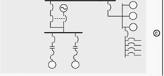
A low-voltage motor control circuit is attached to the automatic transfer switch through a low-voltage bus. Make sure you recognize these symbols. Although we do not know the exact function of the low voltage motor control in this circuit, it is obvious that it is important to keep the equipment up and running. A written specification would normally provide the details of the application.
Below the meter center is a load center or panelboard that is feeding a number of smaller circuits. This could represent a load center in a building that feeds power to the lights, air conditioning, heat and any other electrical equipment connected to the building.
Few more words about SLD
This over-simplified analysis of a single line diagram gives you an idea of the kind of story such diagrams tell about electrical system connections and equipment.
Just keep in mind that although some single line diagrams may appear overwhelming by virtue of their size and the wide variety of equipment represented, they can all be analyzed using the same step-by-step method.
If you’re interested, you can learn more from the following courses:
Learn AC Distribution Panel Drawings: Single-Line Diagrams, Wirings, and Interlocking Schematics
Learn How to Depict Switchgear and Substation Single-Line Diagrams
Reference: Fundamentals of Electrical Distribution by EATON
Related electrical guides & articles


Edvard Csanyi
Hi, I'm an electrical engineer, programmer and founder of EEP - Electrical Engineering Portal. I worked twelve years at Schneider Electric in the position of technical support for low- and medium-voltage projects and the design of busbar trunking systems.I'm highly specialized in the design of LV/MV switchgear and low-voltage, high-power busbar trunking (<6300A) in substations, commercial buildings and industry facilities. I'm also a professional in AutoCAD programming.
Profile: Edvard Csanyi

This information is so precious to me as it helps to clarify some doubts I have! Thank you for sharing your knowledge.
I was just looking up a few electical symbols. Not sure what i did that caused a problem. Very sorry was an accident. Im an electrician not a hacker
The first figure is NOT a one-/single-line diagram. It’s a circuit diagram. The one you find in circuit analysis textbooks.
Thankd for this opportunity given is an eye opening one for me
What is the symbol of VFD.
PLEASE
Variable Frequency Drive
Interesting article, thank you.
How would you you display a power meter on an 11kv SLD?
Thanks so much for sharing your ideas.
Is there a standard symbol list by IEC or ANSI?
We can learn from excellent described in details of this electrical SLD
Please I need trial question for the section
Thank you for this interpretation .It was so easy to understand.
very impressive work
Great job on the symbols! I have an AutoCAD template filled with all of the blocks that I use on a daily basis for one-line, or single line, diagrams. I see a couple of symbols on your page that I don’t have in my template yet; I’ll be making the changes to include them.
The only difference is I use attributes in my blocks instead of values so the power systems design software I use (aeriescars.com) can create the one-line diagrams for me automatically.
Thanks for the great info!
Every Explanation please download options
Sir Very useful Information
Dear Edward .
thank you from more information about electrical SLD. you can tell whats first work in distribution projects.
This is really impactful and easy to understand
Hi may you please send me a pdf copy of this info please. Its very helpful
excellent & simple informative
Can i get a copy please Sir, thank you very much.
Very thorough and informative, great job! Can you please send me PDF file to study? Thank you
Can you please send me pdf copy. TIA :)
Please send me trial access to my e-mail for limited period.
Thanks,
L. Bangar Raju,
cELL NO : +919963348277
Please can you send me the pdf copy to my email [email protected], [email protected]
fantastic article
thanks
Thank you so much EEP & to you Sir For sharing this topic God Bless you all
Please send my email [email protected]
THIS IS A GOOD LITERATURE FOR ELECTRICAL ENGINEERING PERSONS. PLEASE SEND ME THE PDF COPY TO ME
THANKS
Please soft copy about SLD.
Number 52 most commonly represents a circuit breaker especially in drawings made by USA, Mexican, S Korean Engineers. Recently the EU drawings are not with number 52. Also a NO contact or NC contact in an ACB control circuit we names as 52 other than power contacts. Nice Explanation. Ed can you give your email since I had few clarifications to be made, may be you might have published in your earlier versions. My mail is [email protected]. if you send a test mail I would start my mail or else comment here
Thanks for the informative publication
This is real good and educating. Please a PDF copy of this lecture would be appreciated. Thanks
Email: [email protected]
Please send me this Valuable information on my email Address. so that i can give this to my friend and your work is very great.
email – [email protected]
Kindly send me the pdf through my email
[email protected]
Possible send me PDF … [email protected]
Hi,
can someone please tell me the meaning of the number 52 in the square of the drawout circuit breaker symbols on these single line diagrams. It is obviously not the CB number as they are all the same!
Mike
Number 52 represents a circuit breaker according to ANSI/IEEE Standard C37.2 (Standard for electrical power system device function numbers, acronyms, and contact designations).
Good information I need to learn more about this.
Thank you for this insightful and educative information, kindly share with me the PDF.
Super helpful, can you please share the pdf with me…..thanks
Excellent explanation
Hi Sir Edvard can i please ask for a PDF copy of this? thank you very much.
Please send me a PDF file form as this article is very useful as reference.
[email protected]
[email protected]
Very useful information can you send me pdf on my Gmail.id [email protected]
Can you please send me PDF soft copy @ [email protected]
Thanks Edvard Csayani Sir for the excellent work of guidance on Electrical Articles.
Very useful information.Credits to EEP and the author i really appreciate.please kindly send it in pdf format for me through my email [email protected] thanks.
Very informative,would appreciate it if this was sent to my email
Excellent info. For a customized excel template that performs fault calculations, please feel free to email me at [email protected]
Thanks clarity..I love the way you simply the single line diagram..it’s at the simplest form and,every one can understand it well.
Pls send me file on Siemens substation and transmissions line protection
Very good. Just add few lines on why & where use of particular type of line breaking equipment( draw-out / non draw-out CBs / Disconnecting Sws. etc. in conjunction in the same line) need to be shown.
Thank you Edvard Csyani sir for your valuable lessons.EEP has been very helpful,especially for freshers like me who lacks practical experience.I look forward to more important articles.
I was looking for that stuff,
Well explained.
This engineering portal is very helpful for beginner like me.
i really appreciate you sir, i am a beginner, for this reason, i would appreciate if more training on how to interpret SLD is sent to me. thank you sir.
if you can provide with this explanation or simillar to it in pdf format.
This is a great explanation of the ANSI symbols used in SLD’s, I’m used to that standard. However, I’m not so clear on the IEC symbols. Do you have anything that can help out to understand them? A comparison table would be great.
Great blog!! Thanks!
Thanks very much for those information, its very helpful and informative.
However, could you be able to send me a simple systematic drawing from point of generation to transmission and distribution please.
I will really appreciate your help.
Regards
Dats Pukma
Papua New Guinea
Sir, there is this component in a SLD i m given to read which contains a circle with MF written in it, what would that be?
I want Editable Electrical single diagram
The best resource on SLD for beginners. Very lucid!!!!
there is not get PDF option
Nice blog for beginners, keep updating same.
Is it technically recommended/compulsory to connect lighting system to earth leakage???
Mate want to earn some holiday money helping with line diagrams?
Bravo!! The way you simplified the SLDs I don’t think any one can do better then this.
Please send me this file if possible.
Thanks
Excelente me gustaría soy técnico en electricidad recidencial y estudio técnico en electricidad industrial me gustaría el Ártico completo gracias
I really love this site, more informative
Kindly send me this complete article.
My email address is: [email protected]
Great stuff, please add me on your email list.
hi .. i want this file ..(( Learn To Interpret Single Line Diagram (SLD) )) … please send me on my yahoo mail .. thanks …
Very useful information.Credits to EEP and the author i really appreciate.
This is a great explanation of the ANSI symbols used in SLD’s, I’m used to that standard. However, I’m not so clear on the IEC symbols. Do you have anything that can help out to understand them? A comparison table would be great.
Great blog!! Thanks!