
Estimated Study Time: 20 minutes
Auxiliary DC power system
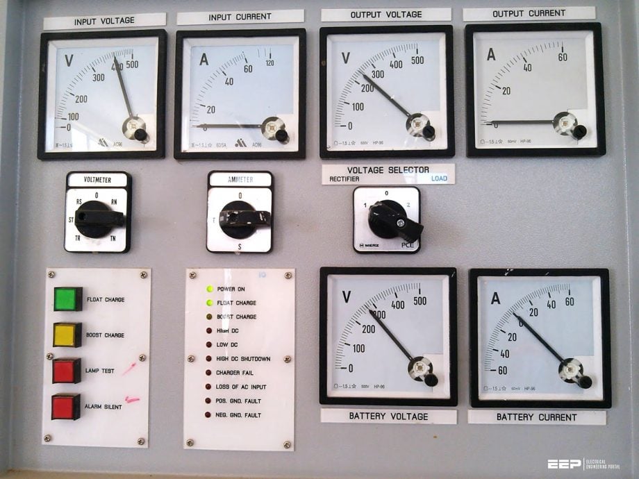
An auxiliary DC power system that consists of a charger, battery bank, DC distribution system, and monitoring system is a critical part of the primary/secondary substation. It is directly associated with the mechanism of fault detection, trip coil operation, remote operation, etc. This article focuses on the primary aspects of optimal sizing of 110V DC charger and power supply system for a typical MV power distribution substation.
 Sizing of DC charger 110V (Auxiliary power supply used in primary/secondary substation) for MV panels
Usually, the auxiliary DC supply used in power substations operates in 110V or 220V, barring some exceptions. To design the complete auxiliary DC supply system for a substation, the design engineer must go through multiple calculations and contemplations.
Through this article, the readers can get an idea to design and put together a complete 110V auxiliary DC supply system for a typical MV power distribution substation by considering multiple factors like- the sizing of the battery bank, calculation of DC loads, rating of battery charger, size and rating of DC distribution panel, etc.
- Introducing a typical 110 V DC auxiliary power supply of a substation
- Major factors for determining the battery size
- Nature of substation loads and their effect on battery sizing
- Impact of battery type in DC charger sizing
- Factors affecting the sizing of the battery charger
- How to calculate the size of the battery bank in an Auxiliary DC power system?
- Sample Calculation for battery bank size
- The decision regarding the charger selection
1. Introducing a typical 110 V DC auxiliary power supply of a substation
The DC auxiliary power supply is required in a substation to ensure that the critical equipment remains in operation continuously even while the primary AC supply is interrupted. When a circuit breaker opens to interrupt the power supply in a radial feeder, this leads to interruption of the power supply to the circuit breaker itself.
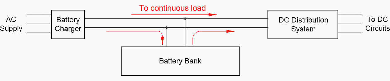
For this, the battery bank stores the energy with the help of an appropriate charger and supplies the DC loads continuously or during power failure via the DC distribution system under proper monitoring and control as per requirement.
Figure 1 – Block diagram of DC system
2. Major factors for determining the battery size
The sizing of the battery bank and an overall DC auxiliary power supply system rely upon various factors. Basically, under normal operation, the charger feeds the DC power to the battery to recover the battery voltage after a discharge while also compensating for any self-discharge losses in the battery. The battery charger also feeds any continuous load on the auxiliary DC system, while the battery storage primarily supports the intermittent loads like trip coils, motors, etc.
The battery size calculation assumes the worst-case scenario in which the battery has to drive the continuous and intermittent load both, caused by charger failure.
Apart from the load profile rating, the battery size depends on the discharge characteristics that result in different Amp-hr ratings to feed the same load. The rate at which the battery degrades due to aging also plays a vital role in enhancing the design margin to compensate for capacity and performance degradation. In the case of a lead-acid battery bank, ambient temperature derates the original capacity of the battery.
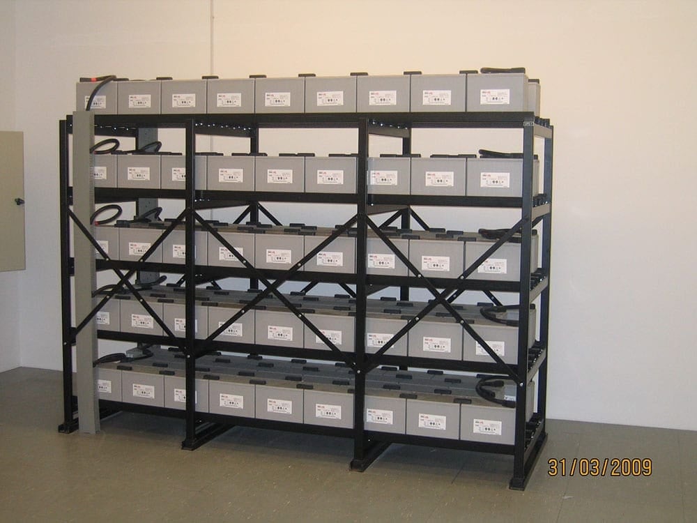
Figure 2 – Substation batteries
3. Nature of substation loads and their effect on battery sizing
The nature of continuous and intermittent substation loads for DC auxiliary power systems has changed over the years because of substantial technology changes. These changes directly impact the sizing of the DC power supply for a new or upgraded substation.
The use of microprocessor-based relays in a modern substation has considerably increased the continuous load on the DC auxiliary power system compared to the use of the previous generation electromechanical relays that operated with the power they derived from the quantities they measured.
The modern microprocessor-based relays require a continuous power supply for real-time data storage and monitoring, communication equipment, HMI devices, etc.
Related electrical guides & articles


Bishal Lamichhane
Electrical Engineer (B.E Electrical, M. Sc Engineering) with specialization in energy systems planning. Actively involved in design and supervision of LV/MV substations, power supply augmentations and electrification for utilities and bulk consumers like airports and commercial entities. An enthusiast and scholar of power systems analysis.Profile: Bishal Lamichhane
