
Estimated Study Time: 50 minutes
HV project design aspects
This technical article covers numerous substation project design elements, lists the steps of the construction process, and examines the environmental impacts and impact mitigation strategies for power transmission and distribution substation projects.
 The life of a power substation project: Design, construction, erection and commissioning
Most projects suffer due to lack of capability of the project proponent and an inept mindset among its engineers and designers that extensive inclusion of environmental mitigation measures in the project design leads to very high construction and O&M costs in the long-run.
At the planning stage itself, land availability is one of the main factors that govern the establishment of a substation project. This involves a contiguous piece of land that can infringe upon scarce populated/forest/cultivated land.
During project construction, deviations to broadly accepted construction practices are quite normal by EPC contractor due to casual approach toward incorporation of environment, health and safety measures in project implementation.
- Top Design Criteria
- Construction Practice, Their Environmental Impacts, Mitigation and Work Process
- Distribution Transformers (below 33 kV)
1. Top Design Criteria
For selection of appropriate site for substation, the following design criteria are usually taken into consideration by project proponents:
Consideration #1 – Site selection should consider seismicity and geography of the local area; the area should not be prone to landslide or located in unstable marshy or flood prone areas.
Consideration #2 – Construction activities do not adversely affect the population living near the proposed substations and does not create any threat to the survival of any community with special reference to tribal community etc.
Consideration #3 – The location of substation does not affect any monument of cultural or historical importance.
Consideration #4 – Transformers and other equipment specifications compliant with government rules/regulations & International Electro-technical Commission (IEC) standards should be followed.
Consideration #5 – Construction techniques and machinery selection to be made with a view to minimize ground disturbance.
Consideration #6 – While planning for substations, drainage plan should be prepared to avoid seepage/leakages and pollution of water sources and natural springs etc.
Consideration #7 – Substation location/design to ensure that noise will not be a nuisance to neighboring properties.
Consideration #8 – Though the standard limits for electromagnetic interference are not prescribed, substation design will incorporate best suited technology and technique to minimize the electromagnetic interference within floor area.
Consideration #9 – Utility should adopt good practices and should always strive for a high standard of housekeeping for its substations and ancillary facilities.
Consideration #10 – Utility should incorporate the best technical practices to deal with environmental issues in its working.
Consideration #11 – Design of substations to include modern fire control systems/firewalls. Oil storage systems, provision of fire-fighting equipment would be located close to transformers, switchgear, etc.
Consideration #12 – For distribution substations, the above items remain the same however, the intensity of impacts get limited due to small size and lower voltages.
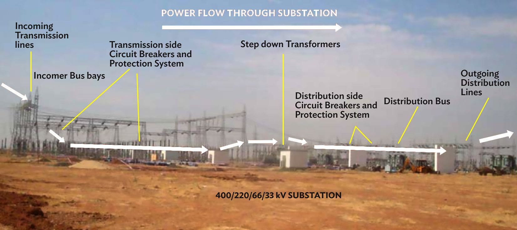
Figure 1 provides a schematic for the power flow from the incoming sub-transmission lines to outgoing distribution lines.
Figure 1 – Schematic Diagram of the Transmission/Distribution System Inside Substation
Go back to the Contents Table ↑
2. Construction Practice, their Environmental Impacts, Mitigation and Work Process
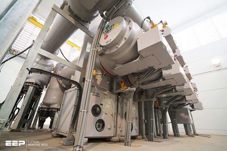
There are two types of electrical substation design that are used depending on the availability of land and its location – Air Insulated Switchgear (AIS) substation design where all equipment is erected outdoors where the land is available; while the Gas Insulated Switchgear (GIS) substation where all equipment besides transformer are erected both indoors and outdoors as shown in Figure 2, 3 and 4 below.
The GIS technology is used where the land is scarce such as highly populated urban areas, high hilly terrains or security reasons.
Figure 2 – GIS based substation equipment in 33/11 kV indoor substation
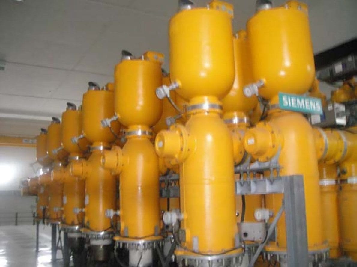
Figure 3 – GIS substation control room layout substation
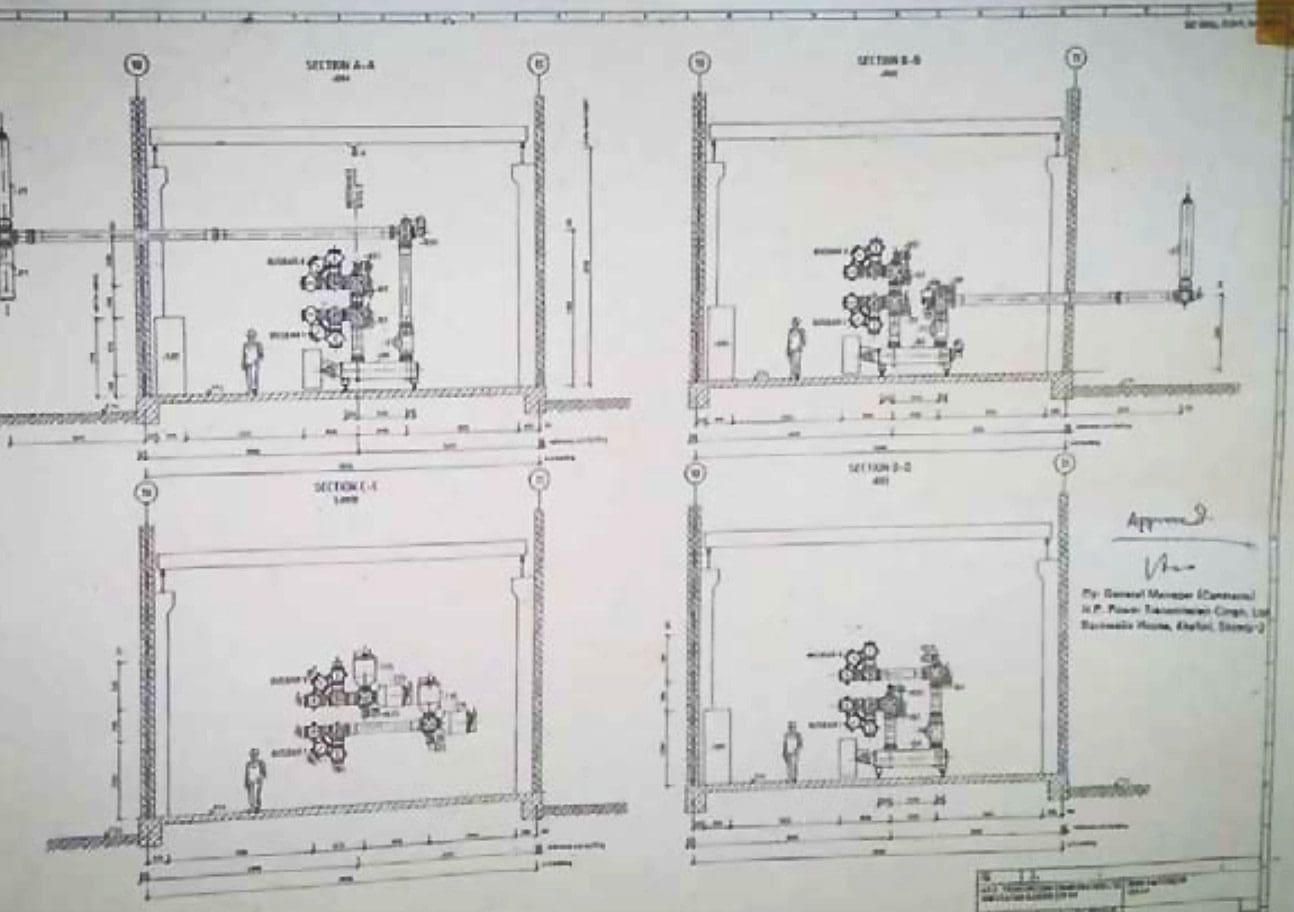
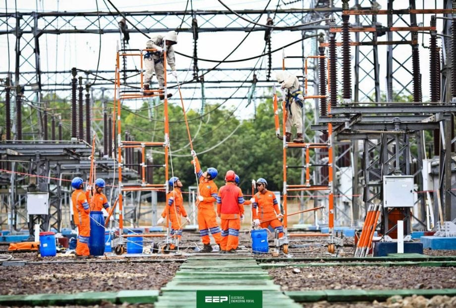
Figure 4 – AIS based substation switchyard equipment station

The AIS substation requires all its components to be situated in the switchyard and air serves as the insulating dielectric medium between different switchgear. Whereas the GIS substations are normally very compact and all equipment are enclosed in Sulphur Hexafluoride (SF6) envelope, a non-toxic greenhouse gas (GHG) used as a dielectric in circuit breakers, switchgear, and other electrical equipment.
GIS station uses very small size of land and building unlike the AIS. The equipment is designed to ensure prevention of even 0.5% leakage of the gas into the environment.
The Flow Chart in Figure 5 displays activities as they progress while constructing a transmission substation. On the left are the “Steps” involved in the process of project implementation such as “Pre Construction, Facilities Setup, Construction, Erection, and Commissioning”.
For example, The construction related environmental impacts usually occur during implementation of “Tasks” 5-17. These “Tasks” are usually performed by the Engineering Procurement and Construction contractor.
This articles provides information about each of the step involved in transmission line design, construction, testing and commissioning, the environment impacts and the proposed mitigation, and work process involved.
Each stage is represented as follows:
- Tasks: lists work undertaken to accomplish the “Steps” shown in Figure 6. This followed by explanation of the task conducted.
- Activity causing Impact and Location: lists the activity undertaken to accomplish each “Task” that impacts the environment and also gives the location of the environmental impact in brackets.
- Impact of activity and its type: describes the impact on environment of each activity and lists it type – temporary, permanent, planning etc. in brackets.
- Mitigation Measure for the Impact: lists environmental mitigation measures taken to mitigate the impact.
- Work process: provides a write up on the work done by EPC contractor for each “Task” and the human aspect involved during task completion.
- Each stage contains pictures from actual working sites that are mapped to each relevant “Activity”.
Figure 5 – Process Flow Chart for Construction of Transmission Substations
Go back to the Contents Table ↑
2.1 Preconstruction
2.1.1 Survey, Alternate Analysis
Reconnaissance Survey: Information on field data required for substation design, distance from community resources – worship place, village common grounds, community center’s schools, hospitals etc. Location of substation as compared to the direction of incomers and outgoing lines is an important factor in determining the site.
Alternative analysis survey: All alternative locations for the substations are proposed and collection of features observed and facilities marked on topographical map (1:50,000). See Figure 6. GPS coordinates are noted for each location finalized for surveys (See Figure 7).
Activity causing Impact and Location: Enumeration of trees for cutting, identification of- locations for digging of soil for foundations for equipment, buildings etc., stacking area for construction material etc. (Location: Substation land)
Impact of activity and its type: Potential impact on physical resources – Topography, possible loss of biodiversity in the area, interference with common property resources, public utilities such as roads, water, sewage facilities etc. (Type: Planning stage)
Impact Mitigation: Avoid biodiversity areas such as location near water body etc. Consider better choice of location to avoid issues regarding common resources with community and public utilities.
Work process: This activity takes the first initial 3-4 months to ascertain the alternative location, the alignment of power lines. Local public resistance to give free tower land may cause delays in preparing alternate analysis case.
Figure 6 – Alternative locations for substations
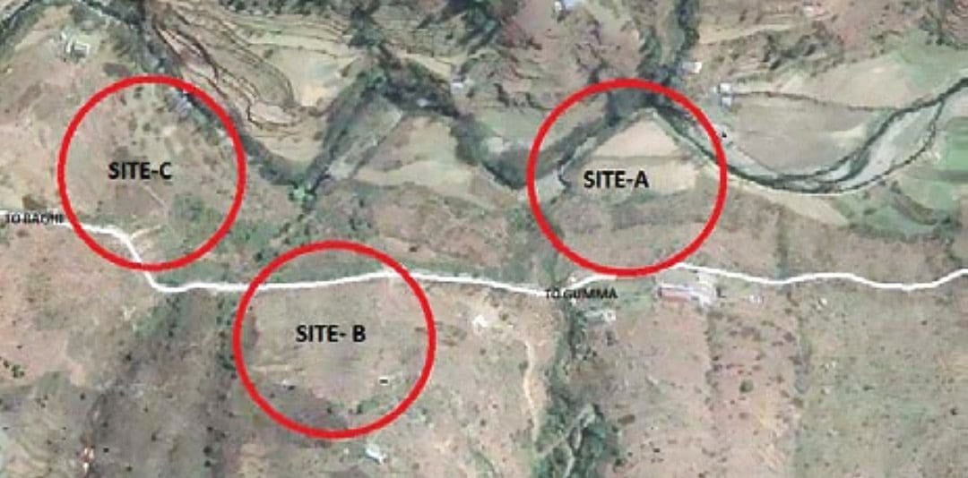
Figure 7 – Marking GPS locations for the future substation

Go back to the Contents Table ↑
2.1.2 Development of Environmental Baseline
Air, water, noise, soil investigation is the important aspect of the substation land in any area, such as hilly, plain level area, or sandy areas. General characteristics of the soil formation to be included in the plan, giving details of weather, clay, gravel, rock etc. that exist in the area as this information has a direct influence on the type of foundation types.
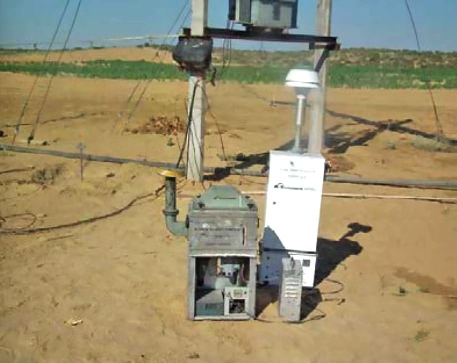
See Figure 8 for noise sampling and Figure 9 for air and dust sampling.
Activity causing Impact and Location: Collection of soil samples by using digging machines as well as collection of water from wells/water sources. (Location: Substation Land)
Impact of activity and its type: Minor impact of collection of soil samples using digging machines on topography or pollution of water source during sample collection. Marshy areas, low-lying areas, riverbeds, earth slip zones that would involve risk to stability of the foundations. (Type: Temporary)
Impact Mitigation: Development of baseline with no project situation a must for monitoring impact of project construction activities. Marshy areas are avoided. Care taken to ensure proper profiling of the ground rock formation and ground water.
Work process: Soil samples taken manually by digging machines and sink new tube well(s) in the planned premises for the substation.
Figure 8 – Noise Measurement

Figure 9 – Air dust samplers
Go back to the Contents Table ↑
2.1.3 Substation Layout
Electrical layout of the site is finalized. (See Figure 10) Facilities layout, selection of benches for substation (various levels in hilly areas), Cutting and filling for levelling land (See Figure 12). Development of drainage, road and other facilities (See Figure 11)
Activity causing Impact and Location: Development of benches by cutting and filling inside the substation sites to ensure proper placement of all equipment. – See Figure 13.
Benching allows voltage level separation by physically locating similar equipment in one bench. (See Figure 13)
(Location: Substation site)
Impact of activity and its type: Planned cutting and filling will lead to soil erosion, runoff of soil, potential water logging, suitable places to dispose excess soil, cutting of trees on the site. (Type: Planning)
Impact Mitigation: Water logged/steep sloped/degraded sites must be avoided while selecting the location of substation. The layout of the site must be such that cutting of trees, soil must be minimized. Extreme slopes need to stabilized for avoiding soil runoff (See Figure 14)
Work process: Preparation of site level contour mapping, coordinates, enumerating number of trees to be cut, plotting location of building, position of various equipment, control rooms, access roads etc. on to the profile sheets.
Figure 10 – Electrical drawing for substation
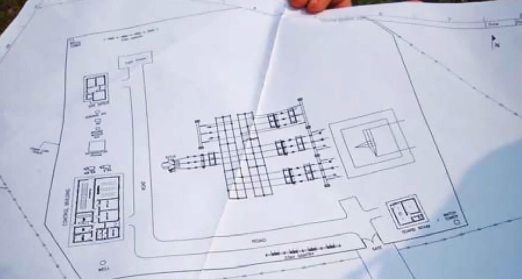
Figure 11 – Substation layout (blue gives drainage plan; rectangles give the benching placement locations of control room, transformers, other equipment, roads, etc.

Figure 12 – Cut and fill of soil for substation land. (blue is current hill profile. Three benches are designed for placement of equipment, transformer, road etc.)
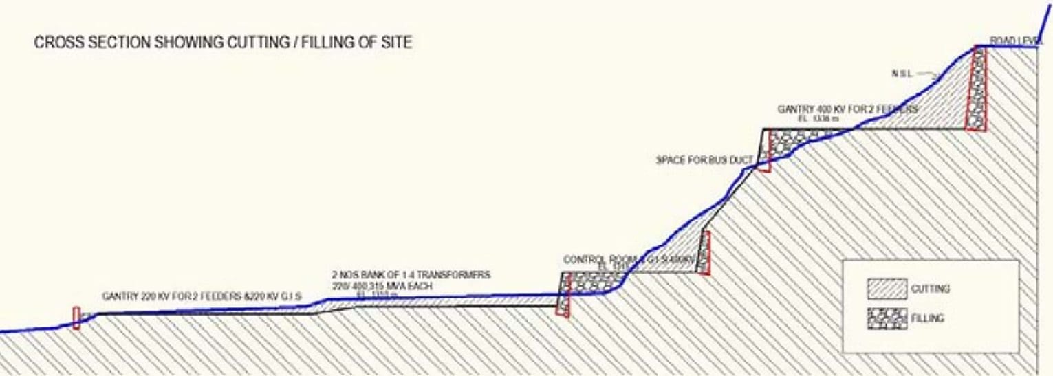
Figure 13 – Benching inside substation land
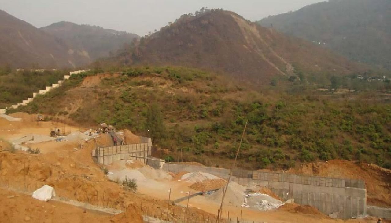
Figure 14 – Proposed sloping substation land

Go back to the Contents Table ↑
2.1.4 Sizing of Equipment, Type and Capacity
Sizing of all substation equipment: The numbers are required in substation according to no. of load centers to be connected and the
corresponding incoming power from power generation sources (either type of generation – renewable and non-renewable sources).
Substation has several equipment that are included in design. See Figures 15 to 18.
- Circuit Breakers (vacuum/oil) (CB),
- SF6 Circuit Breaker,
- Isolators with and without earth Switch,
- Current Transformers (CT),
- Capacitor Voltage Transformers (CVT)/Voltage Transformers (VT),
- Surge Arrestors,
- Bus Post Insulators and Bus bars,
- Potential Transformers (PT),
- Lightning Arrestors (LA),
- etc.
Activity causing Impact and Location: Type of equipment installations/foundations planned as per electrical layout plan (Location: Substation land)
Impact of activity and its type: Potential digging for foundations and surface runoff of soils and any leaching of oils to ground water. (Type: Planning)
Impact Mitigation: Plan for proper location analysis to ensure appropriate distances, installations of equipment, proper access roads etc.
Work process: The equipment will be outdoor for AIS substation and indoor for GIS substation. Such equipment are normally handled using mechanized boom cranes.
Figure 15 – Isolators for incoming (Incomer) lines
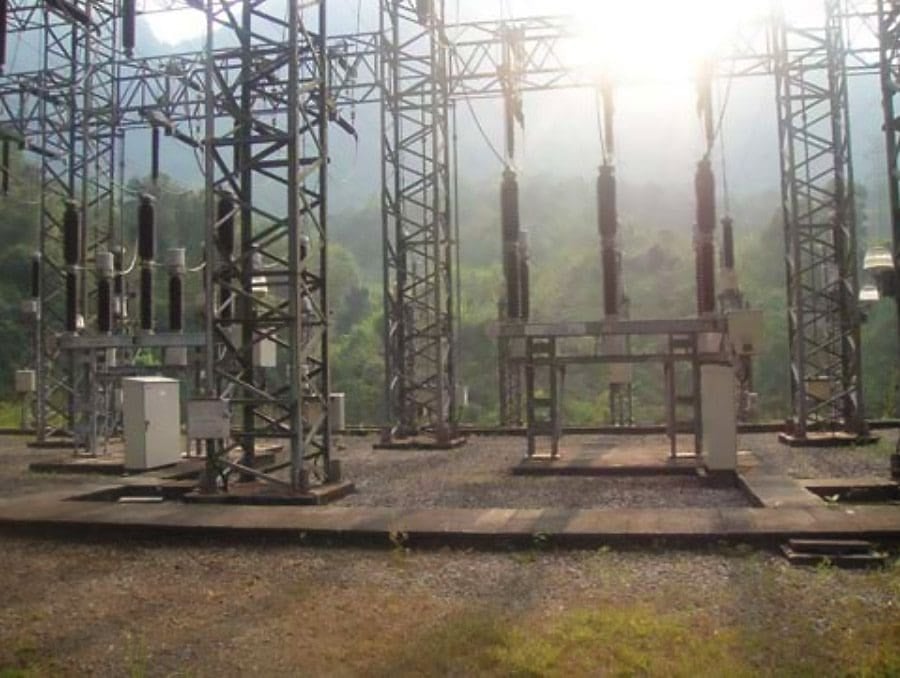
Figure 16 – Other equipment: AIS equipment
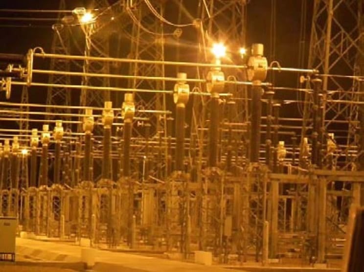
Figure 17 – Line isolators
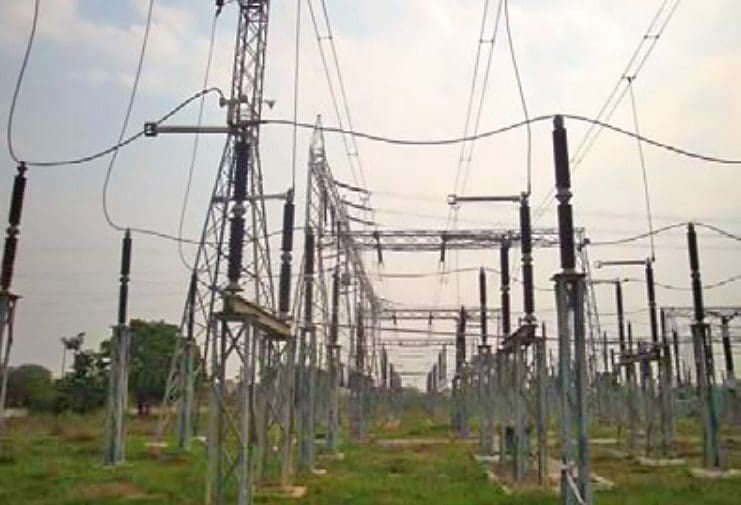
Figure 18 – GIS based substation equipment Indoor
Go back to the Contents Table ↑
2.2 Facilities Set Up
2.2.1 Temporary Worker Camps
The worker camps are temporary in nature and will be used until facilities are fully constructed. These camps are normally made at the substation site and the strength of man-power is between 10-20 workers for a maximum of 6-12 months until construction is complete.
Activity causing Impact and Location: Scatter of kitchen waste, toilet waste, wastewater, scrap, unusable/nonrecyclable waste in camps. Poaching of animal life, fishing, harvesting of wood by workers. (Location: Worker Camp)
Impact of activity and its type: Oils, untreated wastewater, sewage etc. flowing into water body, river, drainage areas from the camps causing impact to surface water, ground water, any aquatic life downstream in the area. The downstream water in river can be polluted making it unfit for bathing or potable water.
Related electrical guides & articles


Edvard Csanyi
Hi, I'm an electrical engineer, programmer and founder of EEP - Electrical Engineering Portal. I worked twelve years at Schneider Electric in the position of technical support for low- and medium-voltage projects and the design of busbar trunking systems.I'm highly specialized in the design of LV/MV switchgear and low-voltage, high-power busbar trunking (<6300A) in substations, commercial buildings and industry facilities. I'm also a professional in AutoCAD programming.
Profile: Edvard Csanyi
