
Estimated Study Time: 11 minutes
Dangerous situations leading to SF6 release
This technical article deals with the assessment of risk to personnel in the case of an abnormal situation leading to an uncontrolled release of SF6 gas into the atmosphere. Generally , such situations occur very infrequently and are very rare. However, let’s discuss such dangerous situations leading to SF6 uncontrolled release: abnormal leakage, internal fault and external fire.
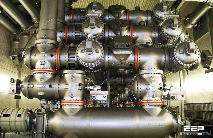 Three abnormal situations leading to an uncontrolled release of SF6 gas (photo credit: hs-augsburg.de)
Table of Contents:
- Abnormal leakage – due to a failure of the SF6 enclosure seals to contain the gas
- Internal fault – resulting from uncontrolled arcing inside the SF6 enclosure
- External fire – giving rise to abnormal leakage
1. Abnormal leakage
The method of risk assessment is similar to that used in section “leakage from SF6 – filled equipment” which deals with normal leakage. The same case study data will be used for high and medium voltage situations.
In the calculations that follow it is assumed that all of the SF6 in one circuit-breaker escapes suddenly and it is again assumed that the switch-room is sealed and that ventilation is inoperative. (see figure 1).
In practice, attention would be drawn to an abnormal leak by underpressure detectors fitted to the CBs. These normally operate around 80% of normal filling pressure, and at this point in time, only 20% of the available SF6 would be in the atmosphere, leading to an SOF2 concentration of 1,8 ppmv.
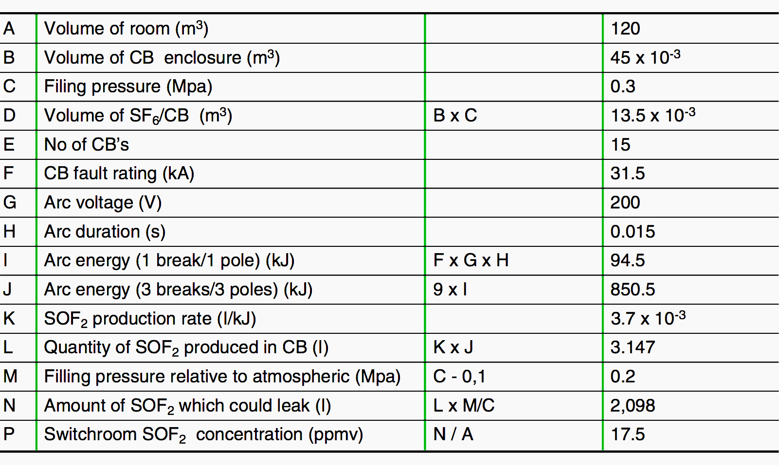
In the case of abnormal leakage of SF6 in a medium voltage indoor substation (see figure 2 ), the SOF2 related to complete escape of SF6 from one CB would reach 17,5 ppmv. The concentration of SOF2 in the switchroom at 20% relative pressure loss (commonly the alarm level) would be 3.5 ppmv.
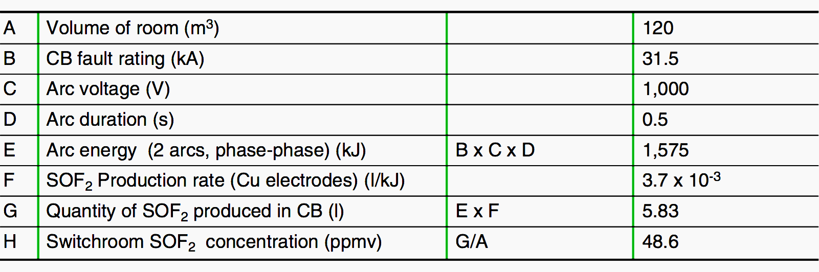
HV Case studied, conditions and calculations
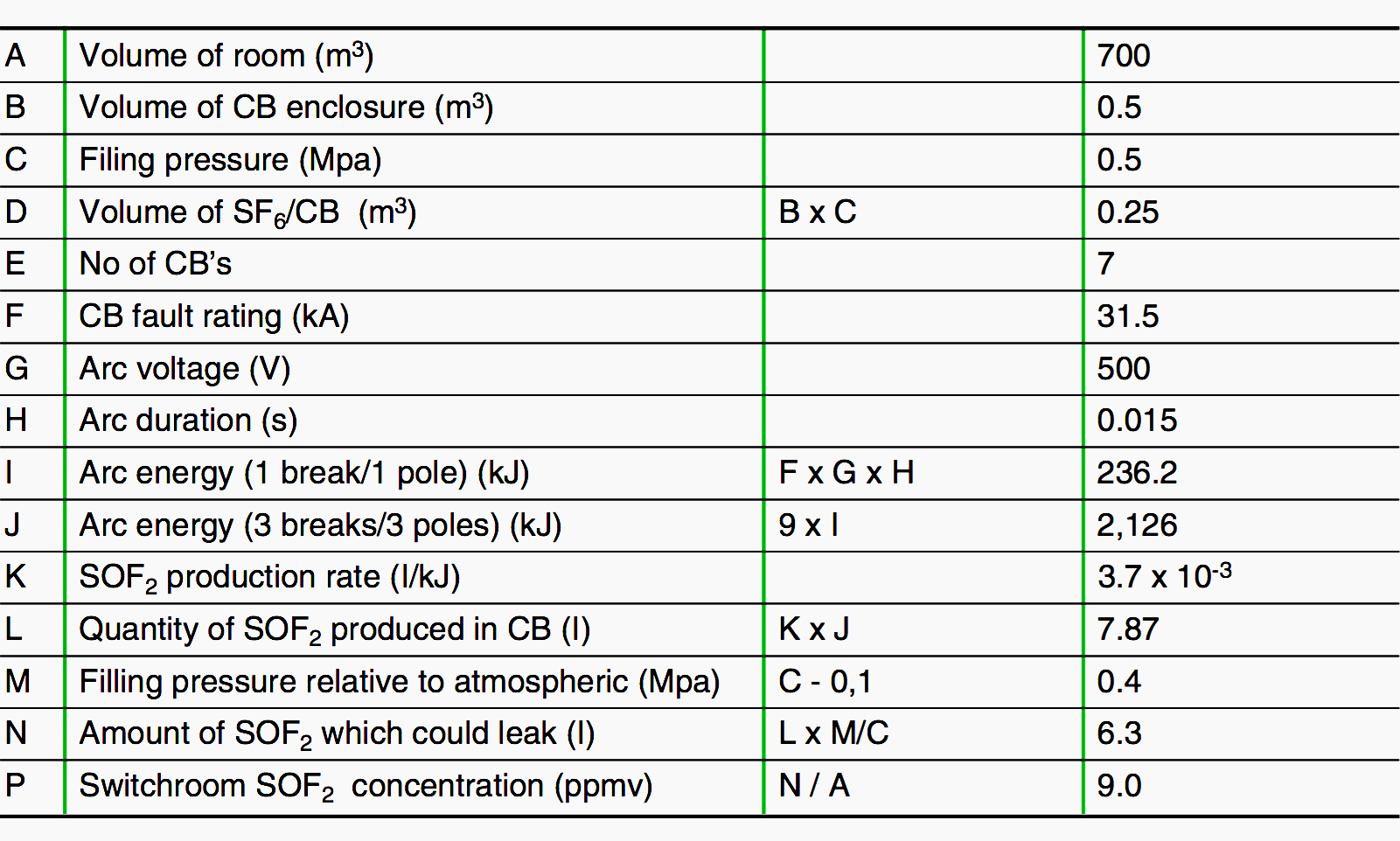
MV Case studied, conditions and calculations
In both cases above, the Threshold Limit Value – TLV for SOF2 (1.6 ppmv) may be exceeded, but by a relatively small factor. Under these circumstances exposure for a short period would present negligible risk.
The pungent, unpleasant odour of SOF2 is noticeable from concentrations of around 1 ppmv and this would mean that, for most people, attention would be drawn immediately to concentrations approaching the TLV. Smell is however not recommended as a detection method.
2. Internal fault
An internal fault can develop when an arc is formed abnormally between the main conductors of an item of switchgear, or between a main conductor and an earthed conducting part. Such faults occur very rarely. Abnormal arcing gives rise to a rapid increase in pressure which can cause hot gases and other materials to be expelled.
There are three possibilities for such faults:
- Internal fault which does not lead to an abnormal release of SF6. This can occur when the energy delivered to the fault is insufficient to lead to burn-through or pressure relief of the enclosure.
- Internal fault where heat from the arc causes the enclosure wall (usually metallic and forming one arc electrode) to melt or vapourise such that a hole is formed. This type of fault is associated mainly with high-voltage GIS equipment.
- Internal fault where the pressure-rise within the enclosure is sufficient to lead to operation of pressure relief devices. This is controlled by a pressure-relief valve or by a well-defined, stress releasing zone of the enclosure, allowing hot exhaust to be directed.
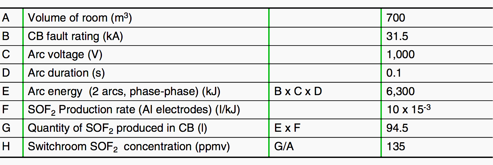
HV Case studied, conditions and calculations
The risks to personnel associated with faults of types 2 and 3 will be considered here. The risks associated with the use of SF6 are evaluated based on the quantity of SOF2 released into the atmoshere.
The following assumptions are made:
- For medium voltage equipment containing small volumes of SF6, it is assumed that the majority of the gas is expelled from the enclosure within 50 ms. This assumption is supported by pressure measurements made during internal fault tests. The quantity of SOF2 formed is therefore calculated using a 50 ms production period.
- For high-voltage equipment a SOF2 production period of 100 ms will be used, because fault- times in high-voltage systems are usually limited to around 100 ms.
- It is assumed that the switch-room is closed to the external environment.
- The effects of adsorbents are likely to be negligible within the time period of interest.
- All of the SOF2 generated during the fault is released into the switch-room. (see fig. 3 & 4).
The results indicate that significant concentrations of SOF2 can be generated within a switchroom. Detailed toxicological data for SOF2 are unfortunately not available but it is known that larger mammals (rabbits) can withstand exposure for one hour at concentrations of up to 500 ppmv.
Other potentially toxic substances are produced during an internal fault including metal and plastic vapours and it can be shown that these inevitable products, which are not related to the use of SF6, can dominate when the overall toxicity of the atmosphere is considered. This applies to any type of switchgear, SF6 filled or otherwise.
If, for example during a busbar fault, only 10 grammes of copper were evapourated into the example medium voltage switchroom atmosphere, the concentration (neglecting the effects of oxidation) would be (mass of Cu / room volume) = 83 mg/m3. The TLV for copper vapour is 0.2 mg/m3. This means that the copper vapour concentration could reach 400 times the TLV.
Similarly, the full vaporisation of only 32 grammes of PVC (equivalent to the insulation from 1.2 m of standard 1 mm2 wire) could give rise to an atmospheric concentration of 100 times the TLV (2.6 mg/m3) of vinyl chloride.
This further strengthens the view that the use of SF6 in switchgear does not significantly add to the risks associated with an internal fault.
3. External fire
Fires in outdoor installations rarely cause problems because of the relative absence of flammable material in the vicinity of the switchgear. In indoor installations, particularly in the case of medium voltage consumer substations, there is a greater risk of fire in the proximity of the switchgear.
Research has shown that fire temperatures rarely exceed 800° C and the temperatures in the region of SF6 enclosures which are protected by metal cladding, are likely to be much lower than this.
Personnel engaged in fighting a fire will be adequately protected by precautions normally used against vapours from burning plastics.
MV Case studied, conditions and calculations
SF6 Gas Leak Detection (VIDEO)
The video shows how a Thermal Imaging Camera (GF306) detects an SF6 Gas leak.
SF6 Leak Detector (VIDEO)
Reference // SF6 properties, and use in MV and HV switchgear by D. Koch (Schneider Electric)
Related electrical guides & articles


Edvard Csanyi
Hi, I'm an electrical engineer, programmer and founder of EEP - Electrical Engineering Portal. I worked twelve years at Schneider Electric in the position of technical support for low- and medium-voltage projects and the design of busbar trunking systems.I'm highly specialized in the design of LV/MV switchgear and low-voltage, high-power busbar trunking (<6300A) in substations, commercial buildings and industry facilities. I'm also a professional in AutoCAD programming.
Profile: Edvard Csanyi

Hi
I just graduated in electrical engineering and started to work in GIS( gas insulated substation ).
I have a question:
when we have sf6 stage 2 in C.B we are going to block C.B’s function (in order to protect C.B) and isolate it from electricity in order to inject sf6 gas into C.B. in the meantime if a fault occurs C.B.F stage 2 will clear the fault by sending DTT( direct transfer trip ) signal and etc.
BUT when we have SF6 stage 2 in other compartments what sort of protection we must and we should consider?
Don’t we suppose to isolate that compartment or bay by sending DTT( if it’s needed for example for P.T and L.A ) and open that bay’s C.B?
thanks in advance for answering my question, I also appreciated if you recommend me some source of study for that situation.