How fast a breaker will trip
Time-current curves are used to show how fast a breaker will trip at any magnitude of current. The following illustration shows how a time-current curve works. The figures along the bottom (horizontal axis) represent current in amperes. The figures along the left side (vertical axis) represent time in seconds.

To determine how long a breaker will take to trip at a given current, find the level of current on the bottom of the graph. Draw a vertical line to the point where it intersects the curve. Then draw a horizontal line to the left side of the graph and find the time to trip. For example, in this illustration a circuit breaker will trip when current remains at 6 amps for 0.6 seconds.
It can be seen that the higher the current, the shorter the time the circuit breaker will remain closed. It can be seen from the time-current curve on the following page that actual time-current curves are drawn on log-log paper, and the horizontal line is in multiples of the breaker’s continuous current rating.
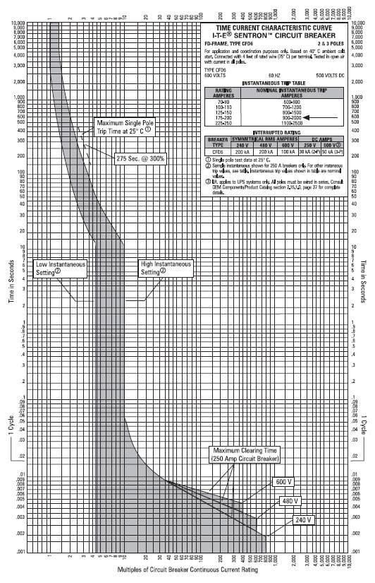
From the information box in the upper right hand corner, note that the time-current curve illustrated on the following page defines the operation of a CFD6 circuit breaker.
For this example a 200 ampere trip unit is selected.
Overload protection component of the time-current curve
The top part of the time-current curve shows the performance of the overload trip component of the circuit breaker. Time-current curves are shown as bands, and the actual performance of any one breaker can fall anywhere within the band. Using the example CFD6 breaker and 200 ampere trip unit, the time the breaker will trip for any given overload can easily be determined using the same procedure as previously discussed.
For example, the breaker will trip between 25 seconds and 175 seconds at 600 amps with a 40°C ambient temperature, which is 3 times the the trip unit rating.
This is illustrated by the time-current curve below.
Instantaneous trip component of the time-current curve
The bottom part of the time-current curve shows the performance of the instantaneous trip component (short circuit) of the circuit breaker. The maximum clearing time (time it takes for breakers to completely open) decreases as current increases. This is because of the blow-apart contact design which utilizes the magnetic field built-up around the contacts.
As current increases the magnetic field strength increases, which aids in opening the contacts. This circuit breaker has an adjustable instantaneous trip point from 900 A to 2000 A, which is 4.5 to 10 times the 200 A trip unit rating. If the trip point adjustment is set to minimum (900 A), and a fault current of 900 amps or greater occurs, the breaker will trip within 1 cycle (16.8 ms). If the trip point setting is set to maximum (2000 A), and a fault current of 900 amps occurs, the breaker will trip between approximately 12 and 55 seconds.
A greater fault current will cause the breaker to trip faster.









Thank you sir for this information.
This is very good site for an Electrical Engineer for their daily base work
These are good notes sir.
Thanks.
This has been quite inspiring.I used to give up easily whenever i came across anything about breaker trip curves,i never had any hope of bumping into so easy to understand material such as above.Thank you so much Mr. Edvard.
You’re welcome! It’s nice to hear this!
Thanks for sharing
How is the energy curve adjusted to the Circuit Braker (MCCB)?
Very good explaination.
plz explain this as per understanding of class 11 student
“If the trip point adjustment is set to minimum (900 A), and a fault current of 900 amps or greater occurs, the breaker will trip within 1 cycle (16.8 ms).” Could you please elaborate further on that because I didn’t get why would it take 1 cycle for the breaker to trip if it is set to a minimum trip point adjustment and a fault of 900A occurs. In the last figure, a vertical line is drawn from the 450% point up till it reaches 1.68 ms (1 cycle). However, the vertical line hits the curve at infinite points and can trip anywhere between 1 ms and 55 seconds. Appreciate your help.
Exactly that is what I see. Vertical bar doesn’t mean that minimum setting is 900A
sir,would you please send me the explanation of characteristic curves of mcb with the graphs that shows the difference between B,C,D curves…. and selection of mcb with protection like close and coarse overcurrent protection
sir , can you please explain . what is low instantaneous and high instantaneous setting
Please send me update/s if available in videos via my email address I like the technical explanations because they are more simplified. Thanks
M.C. Vargas