
Estimated Study Time: 9 minutes
Single line diagram
This technical article explains how to calculate and draw a single line diagram of the three-phase, 60-Hz system power system with generators, motors, transformers and lines.
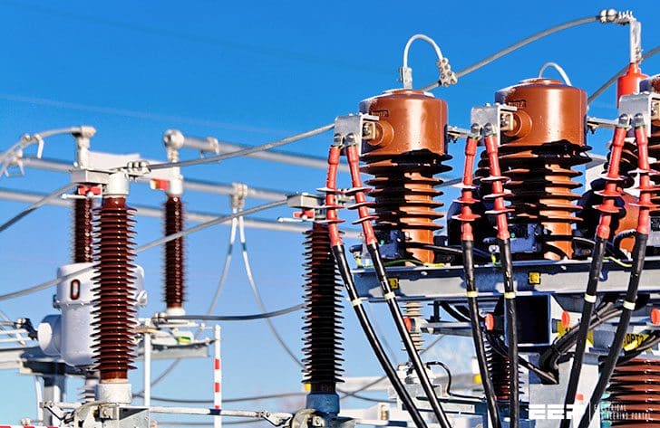 Calculate and Draw a Single Line Diagram For The Power System (Generators, Motors, Transformers & Lines) - photo credit: merko.ee
The following components comprise a simplified version of a power system, listed in sequential physical order from the generator location to the load:
- Two steam-electric generators, each at 13.2 kV
- Two step-up transformers, 13.2/66 kV
- Sending-end, high-voltage bus at 66 kV
- One long transmission line at 66 kV
- Receiving-end bus at 66 kV
- A second 66 kV transmission line with a center-tap bus
- Step-down transformer at receiving-end bus, 66/12 kV, supplying four 12 kV motors in parallel and
- A step-down transformer, 66/7.2 kV, off the center-tap bus, supplying a 7.2 kV motor
Calculation Procedure
1. Identify the Appropriate Symbols
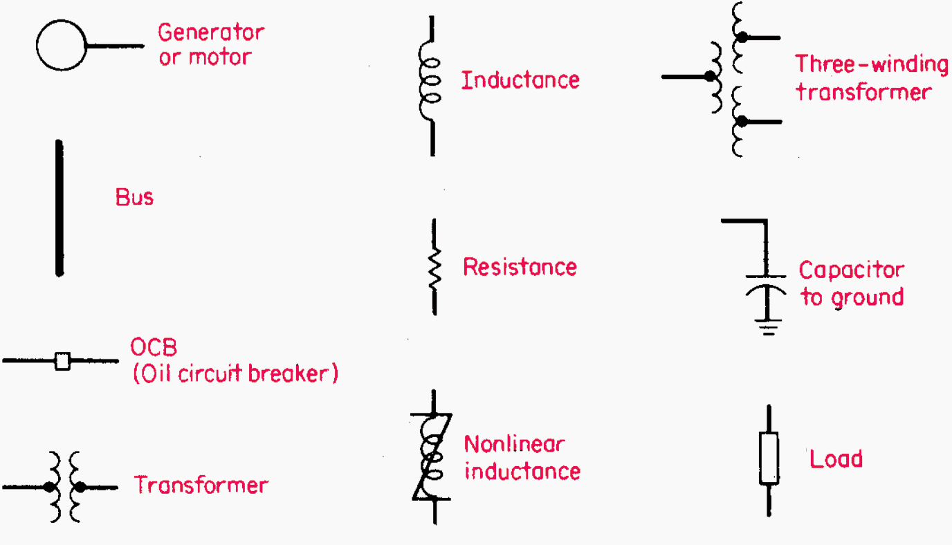
For electric power networks an appropriate selection of graphic symbols is shown in Figure 1 (common power symbols used in single line diagrams):
Figure 1 – Common power symbols used in single line diagrams
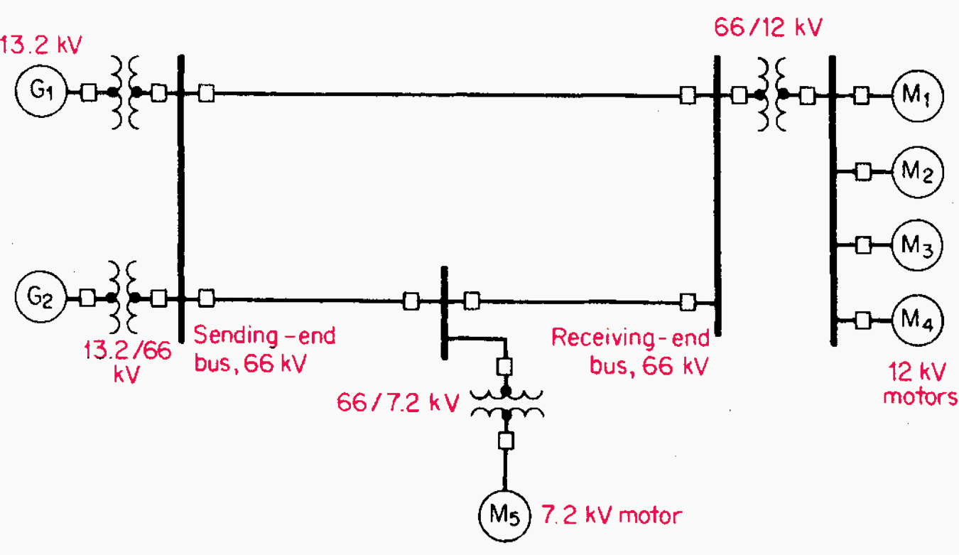
2. Draw the Required System
The system described in the problem is shown in Figure 2. Circuit breakers are added at the appropriate points for proper isolation and disconnection of equipment.
Figure 2 – Three-phase power system represented by single line diagram
Related Calculations
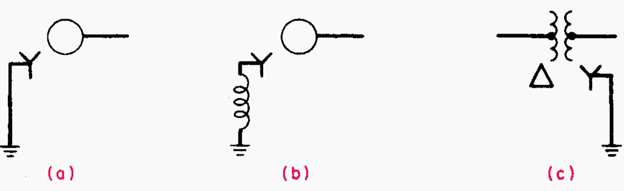
It is the general procedure to use single line diagrams for representing three-phase systems. When analysis is done using symmetrical components, different diagrams may be drawn that will represent the electric circuitry for positive, negative, and zero-sequence components.
This type of notation is shown in Figure 3, (a) Solidly grounded. (b) Grounded through an inductance. (c) The transformer is identified as being delta-wye, with the wye side solidly grounded.
Figure 3 – Identification for wye-connected generator or motor.
Per-unit method of solving of 3-phase problems
The formulation of system quantities as fractions of a defined base unit quantity is known as a per-unit system in the power systems analysis (subfield of electrical engineering). Since the units of measurement remain the same when referred to from one side of a transformer to the other, calculations are made easier.
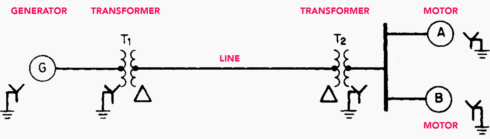
For the system shown in Figure 4, draw the electric circuit or reactance diagram, with all reactances marked in per-unit (p.u.) values, and find the generator terminal voltage assuming both motors operating at 12 kV, three-quarters load, and unity power factor.
Table 1 – Values of power system equipment
| Generator | Transformers (each) | Motor A | Motor B | Transmission Line |
| 13.8kV | 25,000 kVA | 15,000 kVA | 10,000 kVA | – |
| 25,000 kVA 3-phase | 13.2/69 kV | 13.0 kV | 13.0 kV | – |
| X” = 15 percent | XL = 15 percent | X” = 15 percent | X” = 15 percent | X = 65 Ω |
Figure 4 – Single line diagram of electric-power system supplying motor loads. Specifications are given in above table.
Calculation Procedure in 8 steps
1. Establish Base Voltage through the System
By observation of the magnitude of the components in the system, a base value of apparent power S is chosen. It should be of the general magnitude of the components, and the choice is arbitrary. In this problem, 25,000 kVA is chosen as the base S, and simultaneously, at the generator end 13.8 kV is selected as a base voltage Vbase.
(13.8 kV)(69 kV / 13.2 kV) = 72.136 kV
The base voltage of the motors is determined likewise but with the 72.136 kV value, thus:
(72.136 kV)(13.2 kV / 69 kV) = 13.8 kV
The selected base S value remains constant throughout the system, but the base voltage is 13.8 kV at the generator and at the motors, and 72.136 kV on the transmission line.
Watch Video Lesson – Single-line diagram explained in detail
2. Calculate the Generator Reactance
No calculation is necessary for correcting the value of the generator reactance because it is given as 0.15 p.u. (15 percent), based on 25,000 kVA and 13.8 kV. If a different S base were used in this problem, then a correction would be necessary as shown for the transmission line, electric motors, and power transformers.
3. Calculate the Transformer Reactance
It is necessary to make a correction when the transformer nameplate reactance is used because the calculated operation is at a different voltage, 13.8 kV / 72.136 kV instead of 13.2 kV / 69 kV.
(nameplate per-unit reactance) (base kVA/nameplate kVA) (nameplate kV/base kV)2 = (0.11) (25,000/25,000) (13.2/13.8)2 = 0.101 p.u.
This applies to each transformer.
4. Calculate the Transmission-Line Reactance
Use the equation:
- Xper unit = (ohms reactance)(base kVA)/(1000)(base kV)2 =
- Xper unit = (65) (25,000)/(1000)(72.1)2 = 0.313 p.u.
5. Calculate the Reactance of the Motors
Corrections need to be made in the nameplate ratings of both motors because of differences of ratings in kVA and kV as compared with those selected for calculations in this problem. Use the correcting equation from Step 3, above.
X”A = (0.15 p.u.) (25,000 kVA / 15,000 kVA) (13.0 kV / 13.8 kV)2 = 0.222 p.u.
For motor B:
X”B = (0.15 p.u.)(25,000 kVA /10,000 kVA)(13.0 kV / 13.8 kV)2 = 0.333 p.u.
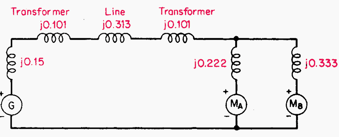
6. Draw the Reactance Diagram
The completed reactance diagram is shown in Figure 5:
Figure 5 – Single line reactance circuit diagram (reactances shown on a per-unit basis)
7. Calculate Operating Conditions of the Motors
If the motors are operating at 12 kV, this represents 12 kV/13.8 kV = 0.87 per-unit voltage. At unity power factor, the load is given as three-quarters or 0.75 p.u.
Iper unit = per-unit power/per-unit voltage = 0.75/0.87 = 0.862 ∠0° p.u.
8. Calculate the Generator Terminal Voltage
The voltage at the generator terminals is:
- VG = Vmotor + the voltage drop through transformers and transmission line
- VG = 0.87∠0° + 0.862 ∠0°(j0.101 + j0.313 + j0.101)
- VG = 0.87 + j0.444 = 0.977 ∠27.03° p.u.
In order to obtain the actual voltage, multiply the per-unit voltage by the base voltage at the generator. Thus,
- VG = (0.977 ∠27.03°) (13.8 kV) = 13.48 ∠27.03° kV
Further Study – How to configure medium voltage switchgear: Key influences and stress variables
How to configure medium voltage switchgear: Key influences and stress variables
Related Calculations
In the solution of these problems, the selection of base voltage and apparent power are arbitrary. However, the base voltage in each section of the circuit must be related in accordance with transformer turns ratios.
Zbase = (base kV)2 (1000) / (base kVA).
For the transmission line section in this problem, Zbase = (72.136)2 (1000) / (25,000) = 208.1
Thus the per-unit reactance of the transmission line equals (actual ohms) / (base ohms) = 65 / 208.1 = 0.313 p.u.
66kv substation control room introduction
Reference: Handbook of el. power calculations by H. Wayne Beaty
Related electrical guides & articles


Edvard Csanyi
Hi, I'm an electrical engineer, programmer and founder of EEP - Electrical Engineering Portal. I worked twelve years at Schneider Electric in the position of technical support for low- and medium-voltage projects and the design of busbar trunking systems.I'm highly specialized in the design of LV/MV switchgear and low-voltage, high-power busbar trunking (<6300A) in substations, commercial buildings and industry facilities. I'm also a professional in AutoCAD programming.
Profile: Edvard Csanyi

My motor pumps are all 3*380v
Please help me help help please please
I have the following three (3) PV-diesel generators hybrid pumping stations and one factory and one residents building at different locations
1. Pump station 1
320KW PV + 600kw(2*300kw) diesel generators and 3*120kw load (motor pumps)- 15 km far away from resident bldg
2. Pump station 2
Same as pump station 1 except it 9km far from resident and 6km far from pump station 1 on the same line with same pump load
3. Pump station 3
Same as pump station 1 except 4km far from pump station 2 and 5km from resident with 4*120kw pump load
4 Resident and factory power –
2.5MW from Diesel generators
Please I want to connect these distributed generation for power sharing purpose.
Please advise me and calculate all necessary information for underground 15kv power transmission line
Thanking in anticipation
Thanks for your brilliant work.
It is very good job and I would like to ask if there is a specific software for SLD drawing and calculations ….thank you
DESIGN DRAW AND EXPLAIN WITH SINGLE LINE DAIGRAM SHOWING THE ARRANGEMENT OF LV PANEL FOR NON LINEAR LOAD OF 2000 KVA WITH ARRANGEMENT OF CAPACITOR BANK AND HARMONIC FILTERS THE OTHER SERVICE LOAD IS 1000 KW THE LOAD SHOULD GET POWER SUPPLY WITHOUT INTERRUPTION TO THE CRITICAL LOADS
On an electrical one line diagram what does Kva + and Kva* mean?
Can you give me the Subtransient reactance Table of motors and generators? thanks!
How to Calculated demand Factor Substation
According to my knowledge the demand factor or maximum demand is equal to Average factor times load factor. I do not know if I am correct can anyone help
Here are some corrections:
EEP – Nov1, 2017 Corrections by Ovide Brudo, Nov 18th
Per-unit method of solving of 3-phase problems
For the system shown in Figure 4, draw the electric circuit or reactance diagram, with all reactances marked in per-unit (p.u.) values, and find the generator terminal voltage assuming both motors operating at 12 kV, three-quarters load, and unity power factor.
Generator Transformers
(each) Motor A Motor B Transmission
Line
13.8kV 25,000 kVA 15,000 kVA 10,000 kVA –
25,000 kVA 3-phase 13.2/69 kV 13.0 kV 13.0 kV –
X” = 15 percent XL = 15 percent X” = 15 percent X” = 15 percent X = 65 Ω
Figure 4 – Single line diagram of electric-power system supplying motor loads. Specifications are given in above table.
Calculation Procedure in 8 steps
1. Establish Base Voltage through the System
By observation of the magnitude of the components in the system, a base value of apparent power S is chosen. It should be of the general magnitude of the components, and the choice is arbitrary. In this problem, 25,000 kVA is chosen as the base S, and simultaneously, at the generator end 13.8 kV is selected as a base voltage Vbase.
The base voltage of the transmission line is then determined by the turns ratio of the connecting transformer:
(13.8 kV)(69 kV / 13.2 kV) = 72.136 kV
The base voltage of the motors is determined likewise but with the 72.136 kV value, thus:
(72.136 kV)(13.2 kV / 69 kV) = 13.8 kV
The selected base S value remains constant throughout the system, but the base voltage is 13.8 kV at the generator and at the motors, and 72.136 kV on the transmission line.
2. Calculate the Generator Reactance
No calculation is necessary for correcting the value of the generator reactance because it is given as 0.15 p.u. (15 percent), based on 25,000 kVA and 13.8 kV. If a different S base were used in this problem, then a correction would be necessary as shown for the transmission line, electric motors, and power transformers.
3. Calculate the Transformer Reactance
It is necessary to make a correction when the transformer nameplate reactance is used because the calculated operation is at a different voltage, 13.8 kV / 72.136 kV instead of 13.2 kV / 69 kV.
Use the equation for correction: per-unit reactance:
(nameplate per-unit reactance) (base kVA/nameplate kVA) (nameplate kV/base kV)2 =
(0.11) (should be 0.15) (25,000/25,000) (13.2/13.8)2 = 0.101 p.u. should be 0.13724 p.u.
This applies to each transformer.
4. Calculate the Transmission-Line Reactance
Use the equation:
• Xper unit = (ohms reactance)(base kVA)/(1000)(base kV)2 =
• Xper unit = (65) (25,000)/(1000)(72.1)2 = 0.313 p.u.
5. Calculate the Reactance of the Motors
Corrections need to be made in the nameplate ratings of both motors because of differences of ratings in kVA and kV as compared with those selected for calculations in this problem. Use the correcting equation from Step 3, above.
For motor A:
X”A = (0.15 p.u.) (25,000 kVA / 15,000 kVA) (13.0 kV / 13.8 kV)2 = 0.222 p.u.
For motor B:
X”B = (0.15 p.u.)(25,000 kVA /10,000 kVA)(13.0 kV / 13.8 kV)2 = 0.333 p.u.
6. Draw the Reactance Diagram
The completed reactance diagram is shown in Figure 5:
TXLs should be j0.13724 (my correction)
Figure 5 – Single line reactance circuit diagram (reactances shown on a per-unit basis)
7. Calculate Operating Conditions of the Motors
If the motors are operating at 12 kV, this represents 12 kV/13.8 kV = 0.87 per-unit voltage. At unity power factor, the load is given as three-quarters or 0.75 p.u.
Thus, expressed in per unit, the combined motor current is obtained by using the equation:
Iper unit = per-unit power/per-unit voltage = 0.75/0.87 = 0.862 ∠0° p.u.
8. Calculate the Generator Terminal Voltage
The voltage at the generator terminals is:
• VG = Vmotor + the voltage drop through transformers and transmission line
• VG = 0.87∠0° + 0.862 ∠0°(j0.101 + j0.313 + j0.101) should be j0.13724 x2
• VG = 0.87 + j0.444 should be j0.58748 = 0.977 ∠27.03° p.u. should be 1.00665 ∠34.03°
In order to obtain the actual voltage, multiply the per-unit voltage by the base voltage at the generator. Thus,
• VG = (0.977 ∠27.03°) (13.8 kV) = 13.48 ∠27.03° kV should be 13.89 ∠34.03°
Related Calculations
In the solution of these problems, the selection of base voltage and apparent power are arbitrary. However, the base voltage in each section of the circuit must be related in accordance with transformer turns ratios.
The base impedance may be calculated from the equation:
Zbase = (base kV)2 (1000) / (base kVA).
For the transmission line section in this problem, Zbase = (72.136)2 (1000) / (25,000) = 208.1
Thus the per-unit reactance of the transmission line equals (actual ohms) / (base ohms) = 65 / 208.1 = 0.313 p.u.
i need building line electrical network design manual or related calculation, Please help me
Have you tried to search?
Hello.
I am just wondering on step 3 Calculate the Transformer Reactance why did you use 0.11 as the nameplate p.u. reactance?Where do we find this information on the details given for the components of the power system?
Thank you.
In step 3 for the Transformer Reactance calcs, you should be using 0.15 pu as the starting reactance (per the table at the beginning), which would result in the new reactance of 0.13724.
Cheers.
Great article. Hoping for some more of these.
Congatulation for your work about single diagram . it’s simple and pratical very good.