
Estimated Study Time: 19 minutes
Step-by-step fault level calculations
This technical article represents the case study of fault level calculations for an MV/LV network using the direct method. There are many advantages of the direct approach, and the main of them is that it directly uses the system single line diagram, equipment data, and basic electrical equations.
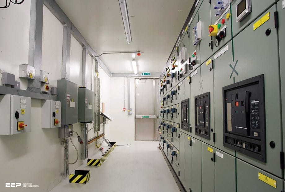 A case study of fault level calculations for a MV/LV network using direct method (photo credit: Portastor via Flickr)
It’s worth mentioning that the direct method of fault level calculations is more straightforward to comprehend than the per-unit method.
For a start, it’s important to prepare a single line diagram of the electrical power supply and distribution network, clearly indicating all the significant network elements (power supply sources, transformers, electric motors, etc.), fault current contributors, short circuit protective devices, etc.
Let’s now describe the network components for which we will calculate the fault levels:
- The 11kV incoming terminals (source fault current)
- The auxiliary transformer’s 11kV terminals
- The 6.6kV switchgear bus
- The service transformer’s 6.6kV terminals
- The 415V PCC panel bus
- The 415V MCC panel bus
- Motor contribution (510kW motor, PF=0.8; eff=85%) at the 6.6kV switchgear bus, assuming that:
- Only one motor in operation
- Both motors in operation
- Motor contribution (110kW motors; IrM = 193.23A) at the 415V PCC panel, assuming five such motors are in operation.
Since an article is quite long, it is divided into four parts. The first part will deal with the calculation of resistances, reactances, and impedances on various network points through fifteen steps. The second part is a table where all these values are nicely summarized. The third part presents a summary of fault current calculation formulae and its value for each of the six network points explained above.
Finally, the fourth part of this article investigates the motor contribution to the overall fault at the 6.6kV switchgear bus and the LV PCC bus.
- Calculation steps:
- 11kV source
- 11kV cable from 11kV source to the auxiliary transformer (C1)
- 11kV source + 11kV Cable
- Conversion of 11kV impedances to the 6.9kV side
- 11kV/6.9kV 7.5MVA transformer (T1) impedance
- Sum of 11kV reflected impedance and T1 impedance
- The connection from the 11kV/6.9kV transformer’s LV terminals to the 6.9kV
- 6.6kV Cable from 6.6kV switchgear to the 6.6kV/433V, 2.5MVA transformer (C2)
- Sum of 11kV reflected impedance, T1 impedance and Cable C2 impedance
- 6.6kV side impedances reflected to the 433V side
- 6.6kV/433V 2.5MVA transformer (T2) impedance
- Sum of 6.6kV side reflected impedance and T2 impedance
- The connection from the 6.9kV/433V transformer’s LV terminals to the 433V PCC
- 1.1kV cable from PCC outgoing to the MCC (C3)
- Sum of 6.6kV side reflected impedance, T2 impedance and cable C3 impedance
- Table of resistances, reactances and impedances
- Summary of fault current calculations
- Motor contribution:
Calculation steps:
Calculation Step #1
11kV source:
The 11kV Source Fault Level is not known. Vide Clause 3.2.2.4 of IS 2026-Part 5: “The short-circuit apparent power of the system at the transformer location shall be specified by the purchaser in his enquiry in order to obtain the value for the symmetrical short-circuit current to be used for the design and the tests. If the short-circuit level is not specified the value given in Table 2 shall be used.”
And vide Table 2 of IS 2026-Part 5, for 11kV system, short circuit apparent power of the system is mentioned as 500MVA.
Table 2 – Short Circuit Apparent Power of the System

Vide Clause 8.3.2.1 of IEC 60909-Part 0, “If a short circuit is fed from a network in which only the initial symmetrical short-circuit power (S”kQ) or the initial symmetrical short-circuit current I”kQ at the feeder connection point Q is known, then the equivalent impedance ZQ of the network (positive-sequence short-circuit impedance) at the feeder connection point Q should be determined by:

In our case, this would be:

Vide the above, in our case:

Calculation Step #2
11kV Cable from 11kV source to the auxiliary transformer (C1)
The cable size given is 350 m of 1R × 1C x 400 mm2 Aluminium Cable per phase (XLPE Cable Assumed).
In our case, the cable length is given as 350m. Hence, the cable reactance will be: 0.0873 × 0.35 = 0.030555 Ω. The cable impedance will be:
√ [(0.035805)2 + (0.030555)2] = 0.047070 Ω
Related electrical guides & articles


Sivakumar K
A professional electrical engineer, having more than 37 years of 'hands-on' experience in the Design, Specification, Selection, Procurement, Inspection, Installation, Testing, Commissioning, Operation, Trouble-shooting & Maintenance of a wide variety of EHV/HV/MV/LV Electrical Equipment in various large industrial projects & process industries. Also, worked/working as a professional electrical trainer, conducting high-end training programmes for industrial electrical professionals & faculty/students of electrical engineering. Published more than 50 technical articles and presented more than 15 technical papersProfile: Sivakumar K
