
Estimated Study Time: 13 minutes
Importance of protecting wind turbines
There is an unabated trend for the utilisation of regenerative energy gained from wind turbines, solar, photovoltaic and biogas plants or geothermal heat. This is an enormous market potential not only for the energy industry but also for the suppliers and the electrical trade and that worldwide.
In Germany meanwhile about 19,000 wind turbines supply a total power of almost 21,000 megawatt which is more than three percent of the power needed. The prognoses for the future turn out to be positive. According to the German wind power institute (Deutsches Windenergie-Institut, DEWI), approximately 4,000 wind turbines are supposed to be installed on the open seas until 2030.
Following topics are covered:
- Danger resulting from lightning effects
- Frequency of lightning strikes
- Standardisation (Germany)
- Protection measures
- Lightning Protection Zones Concept
- Shielding measures
- Earth-termination system
Danger resulting from lightning effects
An operator of these installations cannot afford downtimes. On the contrary, the high capital investments for a wind turbine shall amortize within a few years. Wind turbines are comprehensive electrical and electronic installations, concentrated on a very small area.
Everything, what electrical engineering and electronics offer, can be found: switchgear cabinets, motors and drives, frequency converters, bus systems with actuators and sensors.

It goes without saying that surges can cause considerable damage there. Due to the exposed position and the overall height, wind turbines are exposed to direct lightning effects. The risk of being hit by lightning increases quadratically versus the height of the structure.
Frequency of lightning strikes
The annual number of cloud-to-earth lightning flashes for a certain region results from the well known isokeraunic level. In Europe, a mean number of one to three cloud-to-earth flashes per km and year applies to coast areas and low mountain ranges.
For dimensioning lightning protection installations, it has to be considered that in case of objects with a height of > 60 m, and which are exposed to lightning, also earth-to-cloud flashes can come up, so-called upward flashes, beside cloud-to-earth flashes. This results in greater values as specified in the above formula.

Furthermore, earth-to-cloud flashes starting from high exposed objects carry high charges of a lightning current, which are of special importance for the protection measures at rotor blades and for the design of lightning current arresters.
Standardisation
In Germany, the guidelines of Germanischer Lloyd are the basis for the design of the protection concept.
The German Insurance Association (GDV) recommends in its publication VdS 2010 “Risikoorientierter Blitz- und Überspannungsschutz” (Risk oriented lightning and surge protection) to implement at least lightning protection systems Class II for wind turbines in order to meet the minimum requirements for protection of these installations.
Protection measures
The main concern in this technical contribution is the realisation of lightning protection measures and measures of protection against surges for the electric and electronic devices /systems of a wind turbine.
The complex problems of the protection of rotor blades and swivelling parts and bearings require a detailed examination. They are also producer-specific and type-specific.

DEHN + SÖHNE offers the following engineering and testing service in the company’s impulse current laboratory to provide best solutions for the individual customer (Figure 1):
- Testing of customer-specific, pre-wired connection units for protection of the electrical installation
- Testing of the lightning current carrying capacity of bearings
- Lightning current test at down conductors and receptors of rotor blades
These tests in the laboratory prove the effectiveness of the chosen protection measures and contribute to the optimisation of the “protection package”.
Lightning Protection Zones Concept
The lightning protection zones concept is a structuring measure for creating a defined EMC environment within a structure (Figure 2). The defined EMC environment is specified by the electromagnetic immunity of the used electric equipment.

Being a protection measure, the lightning protection zones concept includes therefore a reduction of the conducted and radiated interferences at boundaries down to agreed values.
For this reason, the object to be protected is subdivided into protection zones. The protection zones result from the structure of the wind turbine and shall consider the architecture of the structure.
It is decisive that direct lightning parameters affecting lightning protection zone LPZ 0A from outside are reduced by shielding measures and installation of surge protective devices to ensure that the electric and electronic systems and devices situated inside the wind turbine can be operated without interferences.
Shielding measures
The nacelle should be designed as a metal shield that is closed in itself. Thus a volume can be obtained inside the nacelle with considerably attenuated, electromagnetic field compared to the outside. The switchgear and control cabinets in the nacelle and, if existing, in the operation building should also be made out of metal.
Earth-termination system
For earthing a wind turbine, the reinforcement of the tower should always be integrated. Installation of a foundation earth electrode in the tower base, and, if existing, in the foundation of an operation building, should also be preferred in view of the corrosion risk of earth conductors.
The earthing of the tower base and the operation building (Figure 3) should be connected by an intermeshed earthing in order to get an earthing system with the largest surface possible. The extent to which additional potential controlling ring earth electrodes must be arranged around the tower base depends on the fact whether too high step and touch voltages must possibly be reduced to protect the operator in case of a lightning strike.

Protective circuit for conductors at the boundary of lightning protection zone LPZ 0A to LPZ 1 and higher Besides shielding against radiated sources of interference, protection against conducted sources of interference at the boundaries of the lightning protection zones must also be provided for reliable operation of the electric and electronic devices.
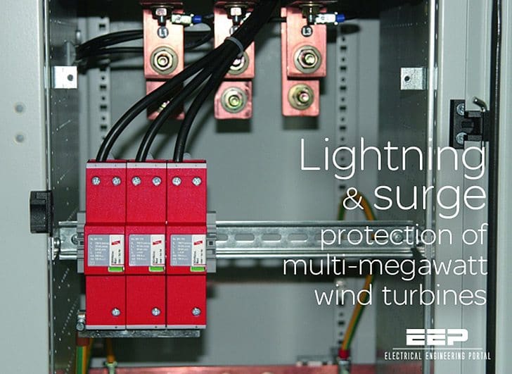
At the boundary of lightning protection zone LPZ 0A to LPZ 1 (conventionally also called lightning equipotential bonding) SPDs must be used, which are capable of discharging considerable partial lightning currents without damage to the equipment. These SPDs are called lightning current arresters (SPDs Type 1) and tested with impulse currents, wave form 10/350 μs.
At the boundary of LPZ 0B to LPZ 1 and LPZ 1 and higher, only low energy impulse currents have to be controlled which result from voltages induced from the outside or from surges generated in the system itself.
Surge protective devices should be chosen according to the operating characteristics of the electric and electronic systems. After the discharge, surge protective devices to be used in the power supply system must be capable of extinguishing safely the follow currents coming from mains afterwards. Beside the impulse current carrying capability, this is the second important aspect of design.
Figure 4 shows lightning current arrester with encapsulated spark gap.


This lightning current arrester can be mounted among bare live system parts in the installation to be protected without having to take minimum distances into account. The protective device DEHNbloc is used, for example, for low voltage lines coming from the wind turbine.
Surge arresters (Figure 5) are dimensioned for loads as they occur in case of inductive couplings and switching operations. Within the scope of energy coordination, they have to be connected downstream of the lightning current arresters. They include a thermally monitored metal oxide varistor.
Considering a single telephone line within the lightning protection zones concept, the partial lightning current on this conductor can be assumed to be blanket 5 %. For a lightning protection system Class III/IV, this would amount to a partial lightning current of 5 kA, wave form 10/350 μs.

Figure 6 – shows the approved multipurpose device BLITZDUCTOR XT, BCT MOD BE as a lightning current and surge arrester. This protective device can be used for protection of equipment in EMC lightning protection zone I and higher. BLITZDUCTOR XT is designed as a four-terminal network and limits both common-mode interferences as well as differential-mode interferences.
It can be fixed directly in the course of terminal blocks or, instead of these terminals, on supporting rails. Its special design allows a space-saving arrangement.
Reference: DEHN – Lightning protection guide
Related electrical guides & articles


Edvard Csanyi
Hi, I'm an electrical engineer, programmer and founder of EEP - Electrical Engineering Portal. I worked twelve years at Schneider Electric in the position of technical support for low- and medium-voltage projects and the design of busbar trunking systems.I'm highly specialized in the design of LV/MV switchgear and low-voltage, high-power busbar trunking (<6300A) in substations, commercial buildings and industry facilities. I'm also a professional in AutoCAD programming.
Profile: Edvard Csanyi

thanks
You’re welcome, glad you liked article.
Great.