
Estimated Study Time: 24 minutes
Introduction to SPD and its role
In an electrical systems, surge protection devices (SPDs) are usually installed in tap-off configuration (in parallel) between the live conductors and the earth. The operating principle of SPD can be similar to that of a circuit breaker.
 Practical tips for installing surge protection devices in low voltage panel (photo credit: bdindustrial.com)
In normal use (no overvoltage): the surge protection device is similar to an open circuit breaker.
When there is an overvoltage: the surge protection device becomes active and discharges the lightning current to earth. It can be likened to the closing of a circuit breaker which would short-circuit the electrical network with the earth via the equipotential earthing system and the exposed conductive parts for a very brief instant, limited to the duration of the overvoltage.
When the overvoltage has been discharged, the SPD automatically returns to its normal state (circuit breaker open).
1. Protection principles
1.1 Protection Modes
There are two lightning overvoltage modes: Common mode and Residual current mode.
Lightning overvoltages appear mainly in common mode and usually at the origin of the electrical installation. Overvoltages in residual current mode usually appear in TT mode and mainly affect sensitive equipment (electronic equipment, computers, etc.).
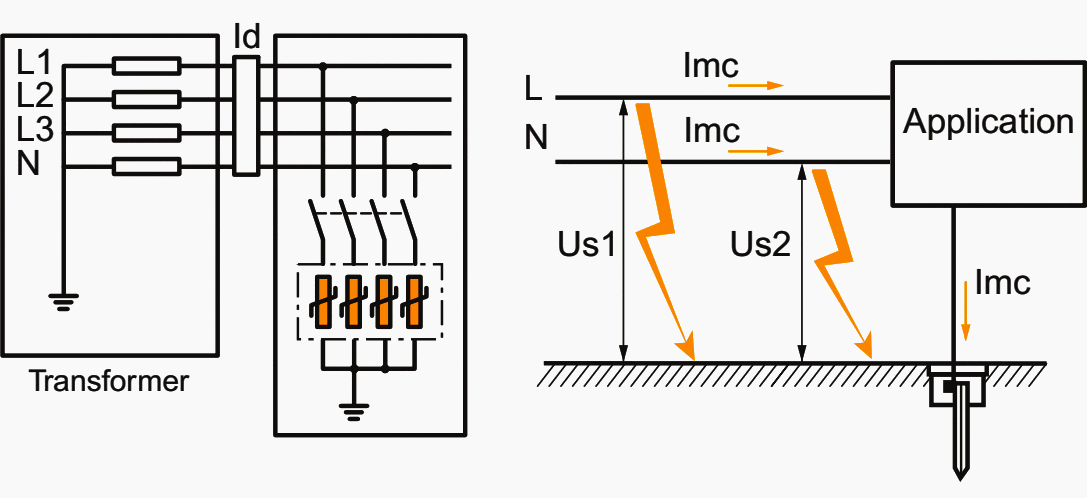
Phase/neutral protection in a TT earthing system is justified when the neutral on the distributor side is linked to a connection with a low value (a few ohms whereas the installation’s earthing electrode is several tens of ohms).

The current return circuit is then likely to be via the installation neutral rather than the earth.
The residual current mode voltage U, between phase and neutral, can increase up to a value equal to the sum of the residual voltages of each element of the surge protection device, i.e. double the level of protection in common mode.

A similar phenomenon may occur in a TN-S earthing system if both the N and PE conductors are separate or not properly equipotential. The current is then likely to follow the neutral conductor on its return rather than the protective conductor and the bonding system.
A theoretical optimum protection model, which applies to all earthing systems, can be defined, although in fact surge protection devices nearly always combine common mode protection and residual current mode protection (except IT or TN-C models).
It is essential to check that the surge protection devices used are compatible with the earthing system.
1.2 Cascaded Protection
Just as overcurrent protection must be provided by devices with ratings appropriate to each level of the installation (origin, secondary, terminal) coordinated with each other, protection against transient overvoltages is based on a similar approach using a “cascaded” combination of several surge protection devices.
Two or three levels of surge protection devices are generally necessary to absorb the energy and limit overvoltages induced by coupling due to high frequency oscillation phenomena.
The example below is based on the hypothesis in which only 80% of the energy is diverted to earth (80%: empirical value dependent on the type of surge protection device and the electrical installation, but always less than 100%).
Spark gap based components designed to discharge most of the energy to earth are combined with varistors or diodes that limit the voltages to levels compatible with the equipment to be protected.
Terminal protection is generally combined with this origin protection. The terminal protection is close to the equipment, provided using proximity surge protection devices.
1.2.1 Combination of several surge protection devices
In order to limit overvoltages as much as possible, a surge protection device must always be installed close to the equipment to be protected 3.
However, this protection only protects equipment that is directly connected to it, but above all, its low energy capacity does not allow all the energy to be discharged.
To do this, a surge protection device is necessary at the origin of the installation 1.
Likewise, surge protection device 1 cannot protect the whole installation due to the fact that it allows an amount of residual energy to pass and that lightning is a high frequency phenomenon.
Depending on the scale of the installation and the types of risk (exposure and sensitivity of equipment, criticality of continuity of service), circuit protection 2 is necessary in addition to 1 and 3.

Note that the first level of surge protection device (1) must be installed as far upstream as possible of the installation in order to reduce as much as possible the induced effects of the lightning by electromagnetic coupling.
1.3 Location of surge protection devices
For effective protection using surge protection devices, it may be necessary to combine several surge protection devices:
- Main SPD ➀
- Circuit SPD ➁
- Proximity SPD ➂
Additional protection may be necessary depending on the scale (line lengths) and the sensitivity of the equipment to be protected (computing, electronic, etc.). If several surge protection devices are installed, very precise coordination rules must be applied.
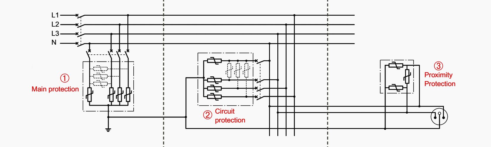
| Origin of installation | Distribution level | Application level |
| The protection at the origin of the installation (primary protection) shunts most of the incident energy (common mode overvoltage carried by the power system) to the equipotential bonding system and to earth. | Circuit protection (secondary protection) supplements the origin protection by coordination and limits residual current mode overvoltages arising from the configuration of the installation. | Proximity protection (terminal protection) performs final peak limiting of the overvoltages, which are the most dangerous for equipment. |
It is important to keep in mind that the protection of the overall installation and equipment is only fully effective if:
- Multiple levels of SPDs are installed (cascading) to ensure the protection of equipment located some distance from the origin of the installation: required for equipment located 30 m or more away (IEC 61643-12) or required if the protection level Up of the main SPD is higher than the category of equipment (IEC 60364-4-443 and 62305-4)
- All networks are protected:
- Power networks supplying the main building and also all secondary buildings, external lighting systems of car parks, etc.
- Communication networks: incoming lines and lines between different buildings
1.4 Protected lengths
It is essential that the design of an effective voltage surge protection system takes account of the length of the lines supplying the receivers to be protected (see table below).
A surge protection device (SPD) is correctly wired when:
- The protected equipment is equipotentially bonded to the same earth to which the SPD is connected
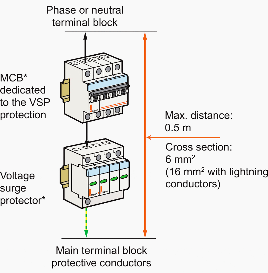
- The SPD and its associated backup protection are connected:
- To the network (live wires) and to the main protective bar (PE/PEN) of the board with conductor lengths as short as possible and less than 0.5 m.
- With conductors whose cross-sections are appropriate for the SPD requirements (see table below).
Table 1 – Maximum line length between SPDe and device to be protected
| SPD position | At origin of installation | Not at origin of installation | |||
| Conductor cross-section | wiring (domestic) | large cables (industry) | wiring (domestic) | large cables (industry) | |
| Composition oft he bonding system | PE conductor | < 10 m | 10 m | < 10 m* | 20 m* |
| meshed/equipotential | 10 m | 20 m | 20 m* | 30 m* | |
* Protection recommended at the point of use if distance is greater
1.4.1 Effect of double voltage
Above a certain length d, the circuit protected by the surge protection device will start resonating when the inductance and capacitance are equal:
Lω = -1 / Cω
The circuit impedance is then reduced to its resistance. Despite the part absorbed by the surge protection device, the residual lightning current I on the circuit is still impulse-based. Its increase, due to resonance, will result in significant increases in the Ud, Uc and Urm voltages.
Under these conditions, the voltage applied to the receiver can double.

Where:
- C – capacity representing the load
- Ld – power supply line inductance
- Lrm – bonding system inductance
The installation of surge protection devices must not adversely affect continuity of service, which would be contrary to the desired aim. They must be installed, in particular at the origin of domestic or similar installations (TT earthing systems), in conjunction with an S type delayed residual current device.
Caution! If there are significant lightning strikes (> 5 kA), the secondary residual current devices may still trip.
2. Installing surge protection devices (SPDs)
2.1 Connecting SPDs
2.1.1 Bonding system or earth connection
Standards bodies use the generic term “earthing device” to designate both the concept of bonding system and that of an earthing electrode, making no distinction between the two. Contrary to received opinion, there is no direct correlation between the value of the earthing electrode, provided at low frequency to ensure the safety of people, and the effectiveness of the protection provided by surge protection devices.
As demonstrated below, this type of protection can be established even in the absence of an earthing electrode.
The impedance of the discharge circuit of the current shunted by the surge protection device can be broken down into two parts.
The first, the earthing electrode, is formed by conductors, which are usually wires, and by the resistance of the ground. Its essentially inductive nature means that its effectiveness decreases with the frequency, despite wiring precautions (limitation of length, 0.5 m rule). The second part of this impedance is less visible but essential at high frequency because it is in fact made up of the stray capacity between the installation and earth.
Of course the relative values of each of these components vary according to the type and scale of the installation, the location of the surge protection device (main or proximity type) and according to the earthing electrode scheme (earthing system).
The surge protection devices should be connected to this bonding system for maximum effectiveness.
The minimum recommended cross-section for the connection conductors takes account of the maximum discharge current value and the characteristics of the end of life protection device.
It is unrealistic to increase this cross-section to compensate for connection lengths that do not comply with the 0.5 m rule. In fact, at high frequency, the impedance of the conductors is directly connected to their length.
In electrical switchboards and large sized panels, it may be a good idea to reduce the impedance of the link by using the exposed metal conductive parts of the chassis, plates and enclosures.
Table 2 – Minimum cross-section of the SPD connection conductors
| SPD capacity | Cross section (mm2) | |
| Class II SPD | S Standard: Imax < 15 kA (x 3-class II) | 6 |
| E Increased: Imax < 40 kA (x 3-class II) | 10 | |
| H High: Imax < 70 kA (x 3-class II) | 16 | |
| Class I SPD | 16 | |
The use of the exposed metal conductive parts of enclosures as protective conductors is permitted by standard IEC 60439-1 as long as this has been certified by the manufacturer.
It is always preferable to retain a wire conductor for connecting the protective conductors to the terminal block or the collector, which then doubles the link made via the the exposed conductive parts of the enclosure chassis.
2.1.2 Connection length
In practice it is recommended that the total length of the surge protection device circuit does not exceed 50 cm. This requirement is not always easy to implement, but using the available exposed conductive parts nearby may help.
* may be installed on the same DIN rail. However the installation will be better protected if both devices are installed on 2 different DIN rails (SPD underneath the protection)
0.5 m rule In theory, when lightning strikes, the voltage Ut to which the receiver is subjected is the same as the protection voltage Up of the voltage surge protector (for its In), but in practice the latter is higher.
In fact, the voltage dips caused by the impedances of the surge protection device connection conductors and its protection device are added to this:
Ut = UI1 + Ud + UI2 + Up + UI3
For example, the voltage dip in 1 m of conductor travelled over by a 10 kA impulse current for 10 μs will reach 1000 V.
Δu = L × di / dt
- di – Current variation 10,000 A
- dt – Time variation 10 μs
- L – inductance of 1 m of conductor = 1 μs
- Value Δu to be added to the voltage Up
The total length Lt must therefore be as short as possible. In practice it is recommended that 0.5 m is not exceeded. In case of difficulty, it may be helpful to use wide, flat conductors (insulated braids, flexible insulated bars).

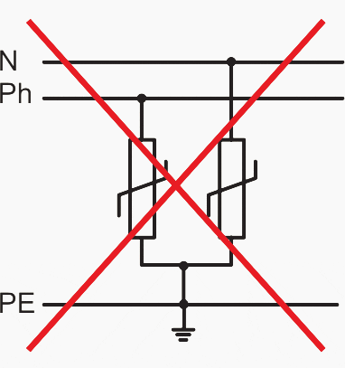
The earth link conductor of the voltage surge protector should not be green/yellow in the sense of the definition of a PE conductor.
Common practice is such that this marking is however frequently used.
SPD wiring configuration #1
Upstream and downstream conductors connected on the voltage surge protector terminal with a common path.

SPD wiring configuration #2
Input and output conductors physically well separated and connected on the same terminal.

SPD wiring configuration #3
Connection conductors too long, output conductors physically separated.
SPD wiring configuration #4
Connection conductors as short as possible with return conductor from the earth terminal close to the live conductors.

2.2 End of life protection of SPDs
The surge protection device is a device whose end of life requires particular consideration. Its components age each time there is a lightning strike.
If the surge protection device exceeds its limitation capacities, it may be destroyed by short-circuiting itself. A short-circuit and overload protection device must therefore be installed in series upstream of the surge protection device (this is commonly referred to the surge protection device branch).

Contrary to certain received opinion, a voltage surge protector must always be protected against possible short-circuit and overload currents. And this applies to all voltage surge protectors, both class II and class I, irrespective of the types of components or technologies used.
This protection must be provided in accordance with the usual discrimination rules.
2.3 Coordinating SPDs
Arranging several surge protection devices in cascade requires them to be coordinated so that each of them absorbs the energy in an optimum way and limits the spreading of the lightning strike through the installation as much as possible.
Primary and secondary surge protection devices must be coordinated so that the total energy to be dissipated (E1 + E2) is shared between them according to their discharge capacity. The recommended distance d1 enables the voltage surge protectors to be decoupled and thus prevents too much of the energy passing directly into the secondary surge protection device with the risk of destroying it.
This is a situation which in fact depends on the characteristics of each of the surge protection devices.
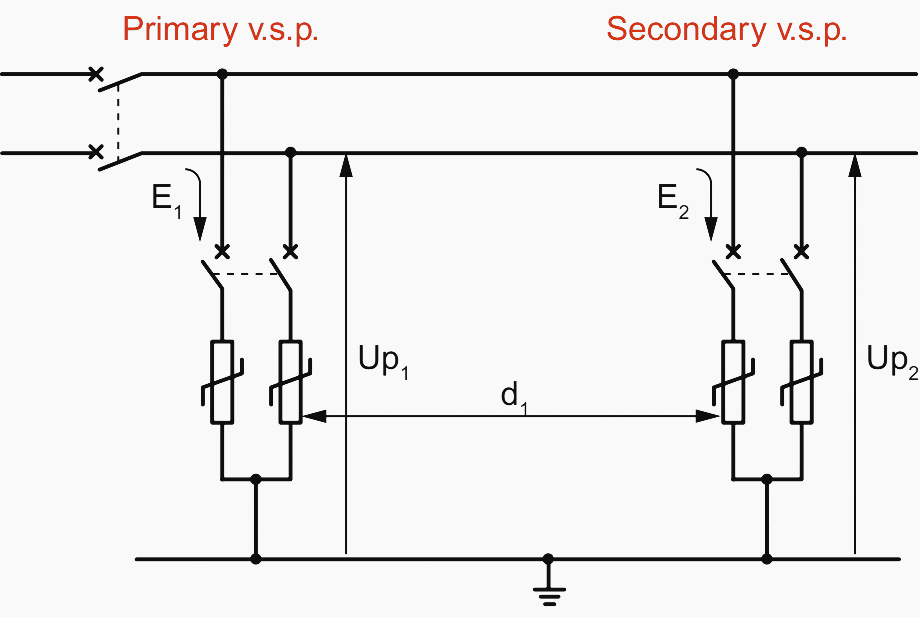
Two identical voltage surge protectors. For example Up: 2 kV and Imax: 70 kA) can be installed without the distance d1 being necessary: the energy will be shared more or less equally between the two surge protection devices. But two different surge protection devices (for example Up: 2 kV/Imax: 70 kA and Up: 1.2 kV/Imax: 15 kA) should be at least 8 m apart to avoid too much demand being placed on the second voltage surge protector.
If not indicated, take d1 min (in metres) as being 1% of the difference between Up1 and Up2 (in volts). For example:
Up1 = 2.0 kV (2000 V) and Up2 = 1.2 kV (1200 V)
⇒ d1 = 8 m min. (2000 – 1200 = 800 >> 1% of 800 = 8 m)
Another example, if:
Up1 = 1.4 kV and Up2 = 1.2 kV ⇒ d1 = 2 m min.
Source: Protection against lightning effects by Legrand
Related electrical guides & articles


Edvard Csanyi
Hi, I'm an electrical engineer, programmer and founder of EEP - Electrical Engineering Portal. I worked twelve years at Schneider Electric in the position of technical support for low- and medium-voltage projects and the design of busbar trunking systems.I'm highly specialized in the design of LV/MV switchgear and low-voltage, high-power busbar trunking (<6300A) in substations, commercial buildings and industry facilities. I'm also a professional in AutoCAD programming.
Profile: Edvard Csanyi

hi
thanks for your complete explain
This is very usefull
How can I manage AC SPD installation on the output of an off-grid photovoltaic HF inverter if I need to bound Null wire to ground?
Apparently, on paper, the segment of SPD that is connected to null wire, appear as în short if I do bounding null to ground bar.
Thank you!
Thank you, very helpful reading mat.
Thanks Mate
Very well put together information .
Cleared out many questions I have got in the subject.
Thank you, Sandor.
in the three phase SPD if we connect Line supply in Neutral then what will happen?
Can you please write an article on ‘how to determine the SPD rating (in KA) for an installation’.
Generious effort to uplift the industry. Good and valuable series of reading material and effective communication on the the subject matter. Thanks and best regards
this is so nice i am doing electrical engineering
but what i need to understand is what is a power surge