
Estimated Study Time: 10 minutes
System intertie transformers (up to 800 kV)
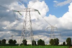
System intertie transformers connect extra high voltage (EHV) transmission systems with different voltages up to 800kV together with the purpose that active as well as reactive power can be exchanged between the systems.
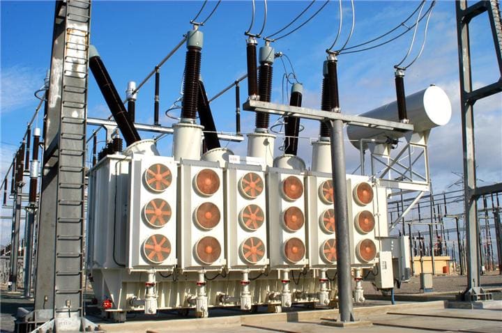
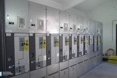
 Connecting transmission systems with system intertie transformers (on photo: ABB's 500 MVA transformers delivered to Oltarzew substation in Poland)
The power rating of such transformers may be quite high, for example 1000 MVA, and they are sometimes made auto-connected in order facilitate the transport from the factory to the site by the lower weight and physical dimensions. In addition the manufacturing cost will be lower compared to a transformer with separate windings.
The turn ratio of such transformers is sometimes fixed, while tappings may be provided in other cases.
The insulation of the windings is normally graded. In separate windings transformers tappings are placed in the neutral end of one of the windings. In auto-connected transformers tappings am typically located in the phases of the low voltage side. See Figure1.
The tappings are sometimes located at the neutral point of auto-connected transformers where the voltage level to earth and the voltage differences between phases am lower than when the tappings are situated at the auto tap. A simpler and cheaper tap changer can then be used.
On the other hand tappings at the neutral will need a larger number of turns in the tapping range to achieve the same variation in the turn ratio as when the tappings are situated at the auto tap or at the high voltage terminal.
- The common winding is connected to the neutral and, as the name indicates, the turns of this winding are common for both sides of the transformer.
- The series winding is connected at one end to the common winding and at the other end to the high voltage terminal.
The high voltage current flows through the series winding. The current flowing in the common winding is the difference between the low voltage and the high voltage current. The current in the common winding flows in the opposite direction to the current in the series winding.
The common winding and the series winding are arranged as concentric cylindrical shells, and the ampere-turns in the two windings are equal in value and opposite in direction.
The advantage of an autotransformer compared to a transformer with separate windings is that the autotransformer requires less material and consequently has smaller total dimensions, lower mass, lower manufacturing costs and lower losses.
The equivalent separate two winding power rating of an autotransformer indicates the magnitude of savings and is given by the following equation:
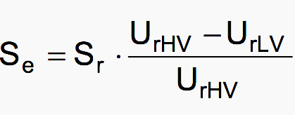
The terms in this equation are the following:
- Se is the equivalent separate two winding power rating of the transformer
- Sr is the power rating of the transformer
- UrHV is the rated high voltage of the transformer
- UrLV is the rated low voltage of the transformer
Equation above states that the equivalent separate two winding power rating is proportional to the difference between the rated high voltage and the rated low voltage of the transformer.
The transformer mass, total dimensions, manufacturing cost and the losses are not directly proportional to the equivalent separate two winding power rating, but all these properties show a decreasing trend with decreasing equivalent separate two winding power rating.
The smaller the difference is between the high and the low voltage, the smaller will be Se and the larger the saving in making the transformer auto-connected instead of a separate winding transformer.
Also the short circuit impedance of the transformer shows a decreasing trend with decreasing difference between the high and the low voltage. When this voltage difference is very small, the short circuit impedance of the transformer becomes also small, which makes the voltage drop in the transformer low. This is an advantage.
On the other hand, the low short circuit impedance in the transformer may make the shod circuit current of the system so high that the mechanical forces in the transformer exceed its withstand ability. A solution to this problem could be to install current limiting reactors in series with the auto-connected transformer.
If for example a single-phase earth fault occurs in one of the circuits, voltage use to earth on the healthy phases will occur in both circuits. If the earth fault occurs in the circuit having the highest voltage, the voltage rise to earth on the healthy phases of the low voltage circuit may become very high, dependant on the difference in system voltage of the two circuits.
Direct earthing of the neutral will mitigate this phenomenon.
One of the commonest applications of the auto connection is in large high voltage system intertie transformers where the system neutral is directly earthed. These transformers are often very large units with 5-limb cores. A tertiary d-connected winding is normally included to provide low zero sequence impedance and triple harmonic magnetising currents to avoid triple harmonics in the magnetic flux and in the induced voltages.
If the tertiary winding is not intended for connection to any power system, one corner of the winding should be solidly earthed to fix the potential of the winding.
It is important that such autotransformers are protected against transient overvoltages on both sides by means of surge arresters between phases and earth.
Within certain geographic areas system voltages on several different voltage levels may exist, often mainly of historical reasons, and there is often a need to connect this systems together by means of transformers.
Due to the large dependence on electric power in the modern society spare transformers for these system connection points are needed.
In order to avoid a large number of spare transformers, each with one specific voltage ratio suitable for use at a particular connection point in the power system, a spare transformer with several different voltage ratios can be made. Such a transformer will then be applicable at several different connection points.
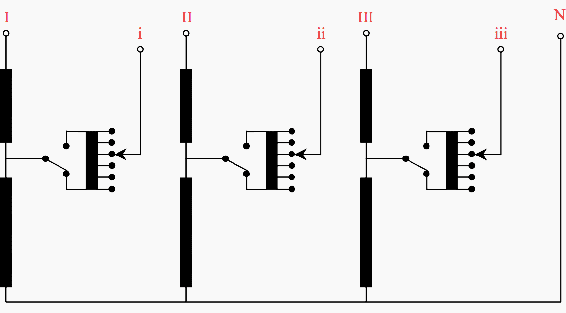
An example of connection diagram for such a transformer is shown in Figure 2.

The transformer is YN-auto-connected with an on-load tap changer in the neutral. The low voltage terminal can be connected to one of several tappings in off-circuit condition. In this way the following voltage ratios are achieved: 400kV to 230kV, 400kV to 132kV, 400kV to 110kV, 230kV to 132kV and 230kV to 107kV.
By means of the on-load tap changer the turn ratio can be adjusted some percents up or down, varying somewhat with the particular system voltages the transformer is used for. The maximum power rating is 450 MVA at voltage ratio 400/230 kV.
At other voltage ratios the power rating is in the range 325 to 200 MVA, dependent on the voltage ratio used.
The transformer has also a delta-connected tertiary winding which limits the zero sequence impedance of the transformer to a reasonably low value. The voltage and power rating of the tertiary winding is dependent on the voltage applied at the high voltage terminal, 400 or 230 kV.
Reference // Transformer handbook by ABB
Related electrical guides & articles


Edvard Csanyi
Hi, I'm an electrical engineer, programmer and founder of EEP - Electrical Engineering Portal. I worked twelve years at Schneider Electric in the position of technical support for low- and medium-voltage projects and the design of busbar trunking systems.I'm highly specialized in the design of LV/MV switchgear and low-voltage, high-power busbar trunking (<6300A) in substations, commercial buildings and industry facilities. I'm also a professional in AutoCAD programming.
Profile: Edvard Csanyi
