
Estimated Study Time: 47 minutes
Critical Aspects and Considerations
In the previous technical article (check here), we delved into primary injection testing and the commissioning of current transformers. We explored the primary and secondary sides of current transformers, learned key concepts and terminology used by protection engineers, and examined components such as the current transformer terminal box, junction boxes, and local control cubicles (LCC) panels that enhance connectivity and control in substations and power plants.
 The good and bad practices in the commissioning of current transformers in a substation
Additionally, we highlighted the significance of polarity marking in current transformers to ensure accurate measurement and proper connection.
Now, in this second part, we will go deeper into the commissioning process of current transformers and discuss various critical aspects and considerations. The topics we will cover include the following:
We will begin by examining the nameplate of current transformers. The nameplate provides essential information for identification and usage, including details such as the total number of cores, protection and metering classes, available taps, rated thermal current, and rated primary and secondary currents.
Adhering to applicable standards is vital to ensure compliance and optimal performance.
Addressing non-compliance between the CT nameplate and the single-line diagram during primary injection testing will be our next point of discussion. It is crucial to rectify any discrepancies to ensure accurate testing and reliable operation of the current transformer.
The importance of checking CT secondary test results and conducting individual tests before performing primary injection testing will be emphasized. This step ensures the integrity and reliability of the CT’s secondary circuit, enabling accurate measurements and effective protection.
We will explore the circumstances that warrant primary injection testing. Understanding when this testing procedure is needed allows engineers to make informed decisions and maintain the reliability of electrical systems.
Another critical consideration is the prohibition of open-circuiting the current transformer’s secondary. This section will highlight the potential risks and detrimental effects of an open circuit, emphasizing the need for proper connections and precautions during testing and operation.
Precautions to be taken during CT primary injection testing will be discussed, highlighting the importance of gradually increasing current for safety, fault detection, equipment protection, and test validation. These precautions ensure a controlled and safe testing environment.
Finally, we will emphasize the significance of a final visual check and CT terminal tightening test. These steps contribute to the overall integrity and reliability of the current transformer, ensuring its proper functioning.
By exploring these topics in this technical article, we aim to provide engineers and professionals with a comprehensive understanding of the commissioning process for current transformers. This knowledge will enable them to conduct accurate testing, ensure reliable operation, and provide effective protection in electrical systems.
- Crucial to know – The nameplate of current transformer:
- Addressing non-compliance of CT nameplate with single-line diagram during primary injection testing
- Importance of checking CT secondary test results and individual tests prior to primary injection testing
- When there is a requirement to conduct a primary injection test?
- Importance of maintaining a short-circuit condition in current transformer (CT) circuits: Avoiding open CT loops and ensuring system safety
- Key verification points in primary injection testing:
- The sign convention for primary-side polarity in current transformers (CTs)
- Case study when single CT pole / phase polarity is wrong
- CT ratio test
- Relay / Meter CT ratio data verification
- Phase verification
- Core verification test
- Ensuring CT circuit integrity: Detecting loose connections in the CT secondary circuit
- Validating protection system functionality: The significance of final trip testing by primary injection test for fault simulation and circuit breaker evaluation
- Verifying CT polarity through primary injection testing
- Essential precautions for conducting CT primary injection testing
- Importance of gradually increasing current in primary current injection testing
- Conducting a thorough visual inspection and CT terminal tightening test
1. Nameplate of Current transformer
Every current transformer (CT) is equipped with a nameplate that contains essential information about its specifications and characteristics. During the commissioning process, it is crucial for engineers to carefully inspect and verify the details mentioned on the CT nameplate, comparing them with the provided schematics or documentation.
The CT nameplate serves as a comprehensive reference, offering valuable insights into various aspects of the transformer.
Here are the key pieces of information typically found on a CT nameplate:
1.1 Total Number of Cores
This indicates the number of separate cores within the CT assembly. Multiple cores may be present in cases where different functions or measurements are required.
1.2 Protection and Metering Classes
CTs are designed to fulfill different purposes, such as protection or metering. The nameplate specifies the applicable classes for each core, ensuring the CT is suitable for its intended use.
Figure 1 – Current transformer (CT) nameplate
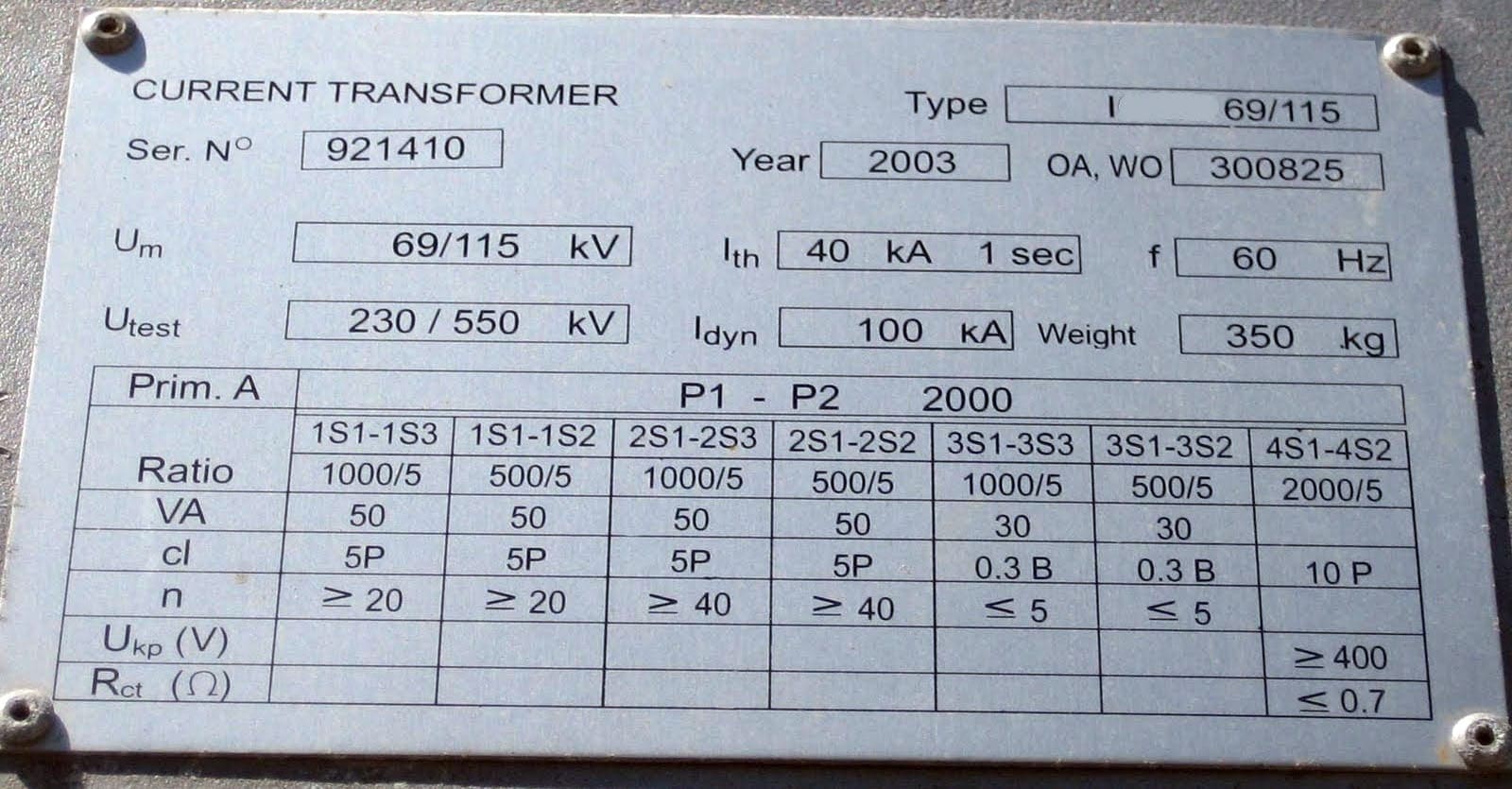
1.3 Taps Available
In some cases, CTs may have multiple tapping points on the primary winding, allowing for adjustment of the transformation ratio. The nameplate specifies the available tap settings, providing flexibility for specific applications.
1.4 CT Secondary and Primary Terminal Details
The nameplate displays the configuration and labeling of the CT’s secondary and primary terminals, indicating how the wiring connections should be made.
1.5 Polarity Details
Polarity information, such as dot notation or specific markings, may be included on the nameplate. This assists in ensuring correct installation and alignment of the CT with the associated electrical circuits and protective devices.
Figure 2 – 110 kV current transformer nameplate
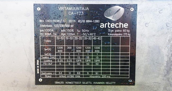
1.6 Rated Thermal Current
This indicates the maximum continuous current that the CT can handle without exceeding its temperature limits. It is an essential parameter for determining the CT’s suitability for the intended application.
1.7 Rated Primary and Secondary Current
The nameplate provides the rated current values for both the primary and secondary sides of the CT. These values determine the transformation ratio and help in selecting the appropriate protection and metering devices.
1.8 Applicable Standards
The nameplate often references the relevant standards or specifications that the current transformer (CT) complies with. This ensures that the CT meets the required industry guidelines for performance, accuracy, and safety. By carefully reviewing the information on the CT nameplate and cross-referencing it with the provided schematics or documentation, commissioning engineers can verify the CT’s specifications and ensure proper integration into the electrical system.
This thorough verification process helps in preventing errors, ensuring optimal performance, and maintaining compliance with industry standards.
Figure 3 – Nameplate of the Current Transformer

Go back to the Contents Table ↑
2. Addressing Non-Compliance of CT Nameplate with Single-Line Diagram During Primary Injection Testing
If you discover that the information on the CT nameplate does not align with the single-line diagram or schematics during a primary injection test, it is important to take appropriate steps to rectify the situation.
Here’s what you can do:
2.1 Double-Check the CT Accuracy!
First, carefully review the CT nameplate and the single line diagram or schematics once again to ensure that there are no misunderstandings or oversights. Verify that you are comparing the correct information and that there are no discrepancies or misinterpretations.
Suggested Reading – The most frequent errors in specifying current transformers (CTs)
The most frequent errors in specifying current transformers (CTs)
2.2 Consult the CT Manufacturer or Supplier!
If there is a clear mismatch between the CT nameplate and the provided documentation, contact the manufacturer or supplier for clarification. They can provide insights into the discrepancy and advise on the necessary steps to resolve the issue.
2.3 Seek Guidance From Experts!
Consult with experienced electrical engineers or professionals who are knowledgeable in current transformers and electrical system design. They may be able to provide guidance on how to reconcile the conflicting information and suggest appropriate solutions.
Related electrical guides & articles


Muhammad Kashif
Muhammad Kashif Shamshad is an Electrical Engineer and has more than 17 years of experience in operation & maintenance, erection, testing project management, consultancy, supervision, and commissioning of Power Plant, GIS, and AIS high voltage substations ranging up to 500 kV HVAC & ±660kV HVDC more than ten years experience is with Siemens Saudi Arabia.Profile: Muhammad Kashif
