Water treatment plants
For both drinking water and wastewater treatment, 4 different sizes of plants have been distinguished. The size of plants can be expressed in quantity of treated water per day, or in corresponding number of inhabitants.
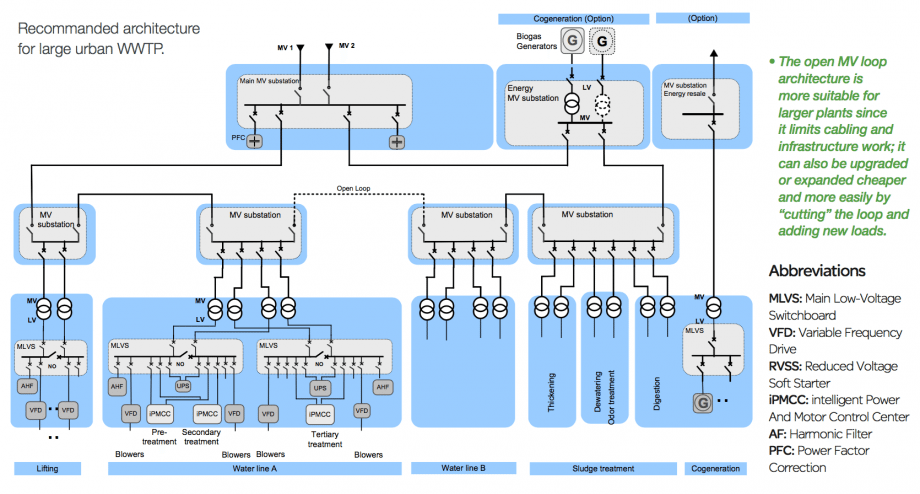
Four different types of (waste) water treatment plants have been distinguished, depending on destination and size:
- T1 – Autonomous water treatment plant // See single-line diagram
- T2 – Small water or wastewater treatment plant // See single line diagram
- T3 – Medium sized water or wastewater treatment plant
- See single line diagrams //
– Double-radial architecture and
– Open medium voltage loop
- See single line diagrams //
- T4 – Large water or wastewater treatment plant
- See single line diagrams //
– Radial-double feed
– Open medium voltage loop
- See single line diagrams //
| Characteristics | T1 | T2 | T3 | T4 |
| m3/day (drinking water or waste water) | 1K-5K | 5K-50K | 50K-200K | 200K-1000K |
| Inhabitants | 1K-10K | 10K-100K | 100K-500K | 500K-1000K |
| Power demand | 25-125 kVA | 125-1250 kVA | 1.25-5 MVA | 5-25 MVA |
Electrical Distribution
Guidance is given for the selection of Electrical Distribution architecture in water treatment plants. This includes the selection between different possible configurations of MV and LV circuits and the implementation of back-up power sources.
The most relevant characteristics of the electrical installation are taken into account, such as typology, power demand, sensitivity to power interruptions, …
- Connection to the utility network
- MV circuit configuration
- Configurations of LV circuits
- Backup generators
- Presence of uninterruptible power supply (UPS)
Connection to the Utility network
4 most commonly used configurations for connection are as follows, in the order of increasing power demand and service reliability //
- LV or MV single-line service
- MV ring-main service
- MV duplicate supply service
- MV duplicate supply service with double busbar
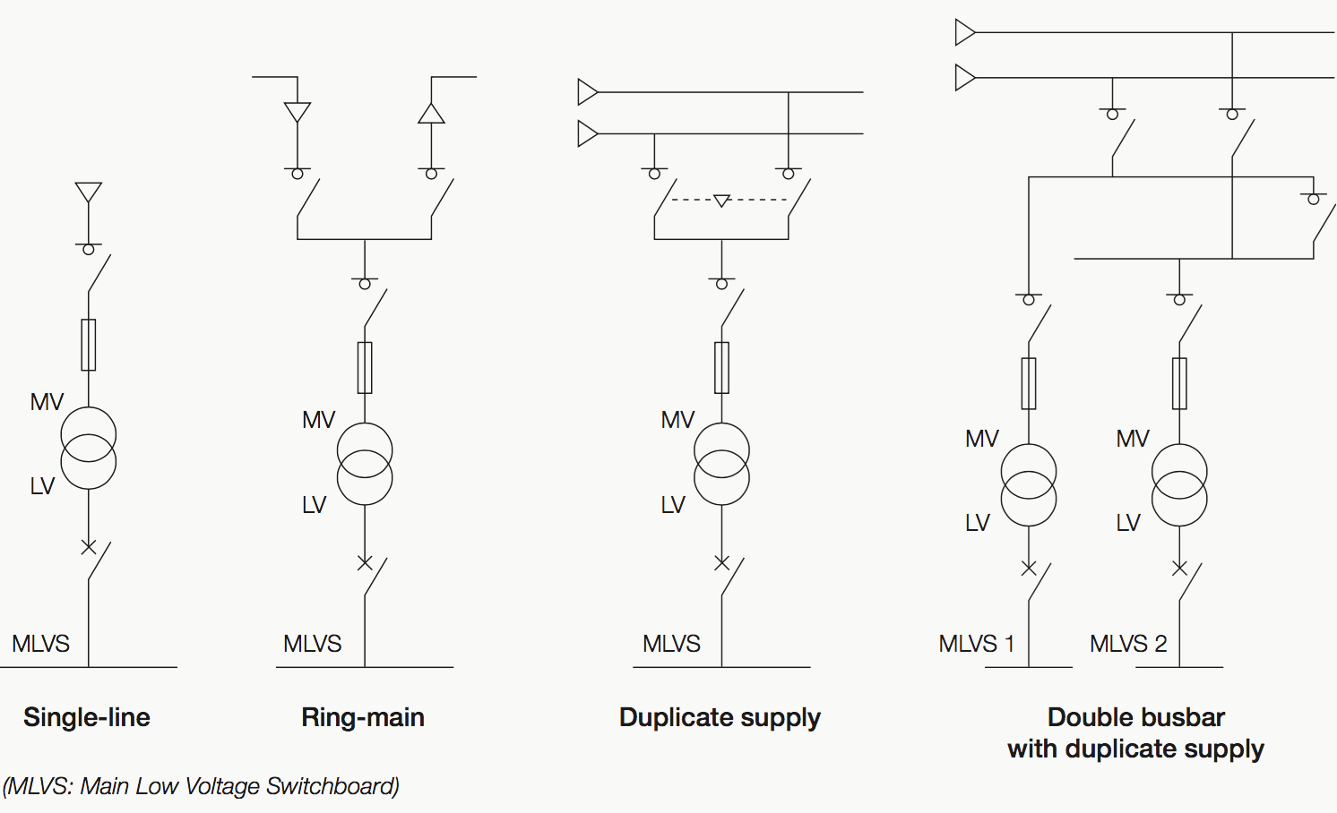

Metering, protection and disconnection devices, located in the delivery substations are not represented on the following diagrams. They are often specific to each Utility company and do not have an influence on the choice of installation architecture. For each connection, one single transformer is shown for simplification purposes, but in practice, several transformers can be connected.
For the different possible configurations, the most probable and usual set of characteristics is given in the following table:
| Characteristic to consider | Configurations | ||||
| LV | MV | MV | MV | MV | |
| Single line | Ring main | Duplicate supply | Duplicate supply with double busbar | ||
| Site topology | Autonomous water treatment plant T1 Remote pumping station P1, P2 | Water treatment plant T2 Remote pumping station P3 | Water treatment plant T3 Desalination T2 | Water treatment plant T4 Desalination T3 | Desalination T4 |
| Service reliability | Minimum | Minimum | Standard | Standard | Enhanced |
| Power demand | < 250 kVA | < 1250 kVA | 1.25-5 MVA | 5-25 MVA | > 25 MVA |
The connection configurations may differ from the above table due to particular constraints relative to water industry plants – spread-out configuration and suburban location.
Go back to Water Treatment Plants Topics ↑
MV circuit configuration
The three main possible connection configurations are as follows:
- Single feeder, one or several transformers,
- Open ring, one MV substation,
- Open ring, 2 MV substations.
The basic configuration is a radial single-feeder architecture, with one single transformer. In the case of using several transformers, an open ring is commonly realized for improved power availability.
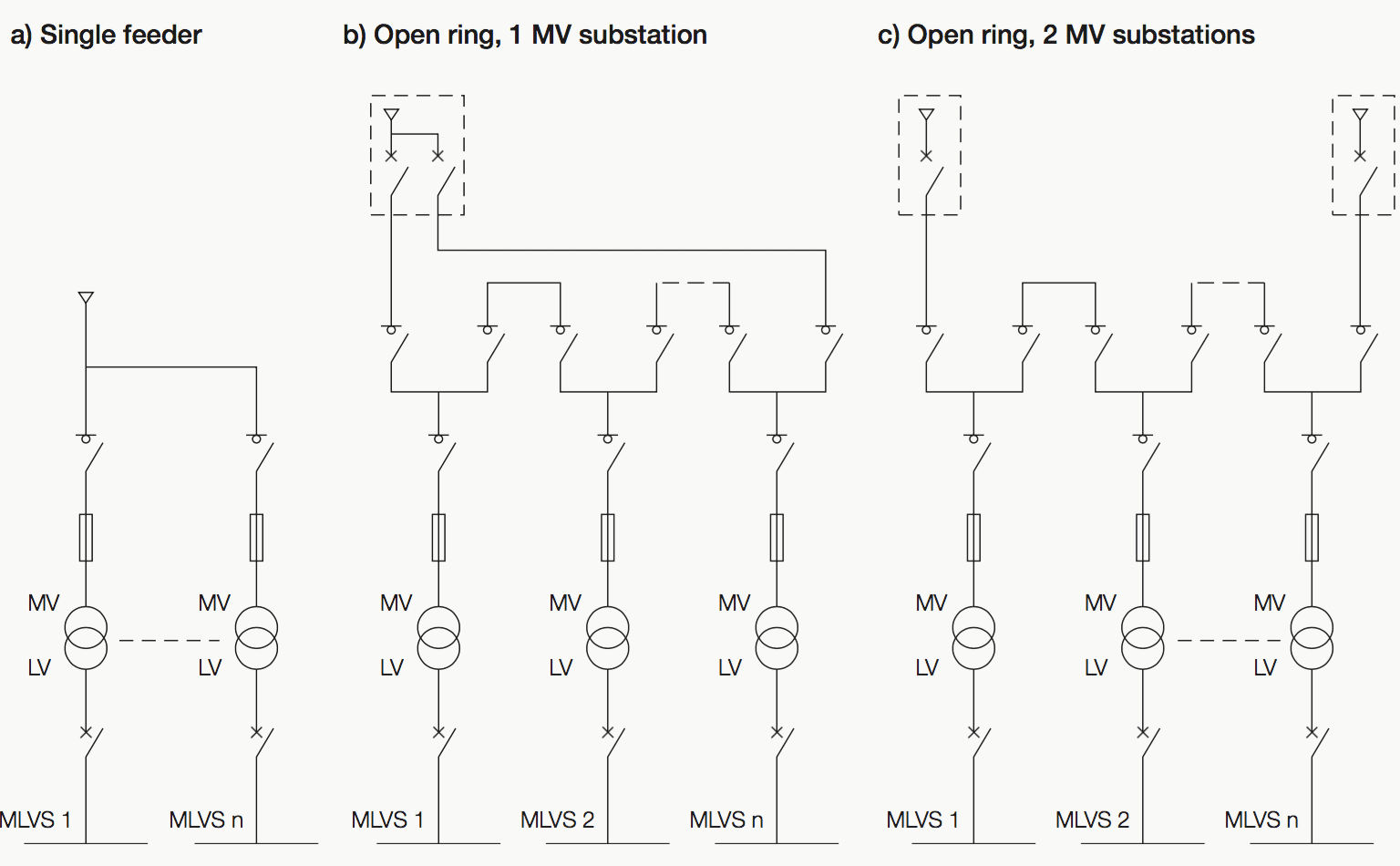

High power motors may be directly supplied at MV for reduction of cable size. The preferred basic configuration comprises one single substation. However, a larger number of substations is possible in some circumstances:
- A large site,
- A site with several different process lines,
- A total power higher than 5 MVA,
- A need for redundancy, to cope with a natural disaster for example.
The preferred configuration of MV/LV transformers comprises a single transformer supplying the total power of the installed loads.
Certain factors contribute to increase the number of transformers (> 1), preferably of equal power:
- A high total installed power (> 1250 kVA): practical limit of unit power (standardization, ease of replacement, space requirement, etc…),
- A large site. The setting up of several transformers as close as possible to the distributed loads allows the length of LV connections to be reduced,
- A need for partial redundancy (down-graded operation possible in the case of a transformer failure) or total redundancy (normal operation ensured in the case of a transformer failure),
- Separating of sensitive and disturbing loads (e.g.: IT equipment, motors),
- Different independent process lines,
- Supply of MV motors,
- Installation scalability (different identical process lines).
For the different possible configurations, the most probable and usual set of characteristics is given in the following table:
| Characteristic | Configurations | ||
| Single feeder 1 substation 1 transformer | Single feeder 1 substation N transformers | Open ring 1 or 2 substations N transformers (different powers) | |
| Plant topology | Small T2 | Medium T3 | Large T4 |
| Power demand | < 1250 kVA | 1.25 – 5 MVA | > 5 MVA |
| Load distribution | Uniform | Intermediate | Localized high power loads |
| Maintainability | Minimum | Standard | Enhanced |
| Disturbance sensitivity | Long interruptions acceptable | Short interruption acceptable | Short interruption acceptable |
Go back to Water Treatment Plants Topics ↑
Configuration of LV circuits
Here are the main possible configurations, to be selected according to the requested level of power availability //
Radial single feeder configuration
This is the reference configuration and the most simple. A load is connected to only one single source. This configuration provides a minimum level of availability, since there is no redundancy in case of power source failure.

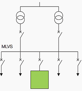
Two-pole configuration
The power supply is provided by 2 transformers, connected to the same MV line. When the transformers are close, they are generally connected in parallel to the same Main Low Voltage Switchboard (MLVS).

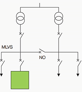
Variant: Two-pole with two ½ MLVS and NO link
In order to increase the availability in case of failure of the busbars or authorize maintenance on one of the transformers, it is possible to split the MLVS into 2 parts, with a normally open link (NO). This configuration generally requires an Automatic Transfer Switch (ATS).

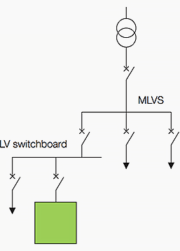
Sheddable switchboard (simple disconnectable attachment)
Sheddable circuits can be connected to a dedicated switchboard. The connection to the MLVS is interrupted when needed (overload, generator operation, etc…)

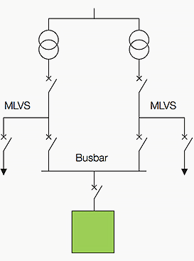
Interconnected switchboards
If transformers are physically not too far from one another, they may be connected by a busbar trunking. A critical load can be supplied by one or other of the transformers.
The redundancy can be //
- Total: each transformer being capable of supplying the whole installation,
- Partial: each transformer only being able to supply part of the installation. In this case, part of the load must be disconnected (load- shedding) in the case of one of the transformers failing.

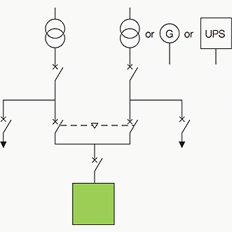
Double-ended power supply
This configuration is implemented in cases where maximum availability is required. The principle involves having 2 independent power sources, e.g.:
- 2 transformers supplied by different MV lines
- 1 transformer and 1 generator
- 1 transformer and 1 UPS
An automatic transfer switch (ATS) is used to avoid the sources being parallel connected. This configuration allows preventive and curative maintenance to be carried out on all of the electrical distribution system upstream without interrupting the power supply.

Configuration combinations
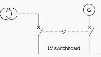
An installation can be made up of several sub-assemblies with different configurations, according to requirements for the availability of the different types of load. E.g.: generator unit and UPS, choice by sectors (some sectors supplied by cables and others by busbar trunking).
Go back to Water Treatment Plants Topics ↑
Back-up generators
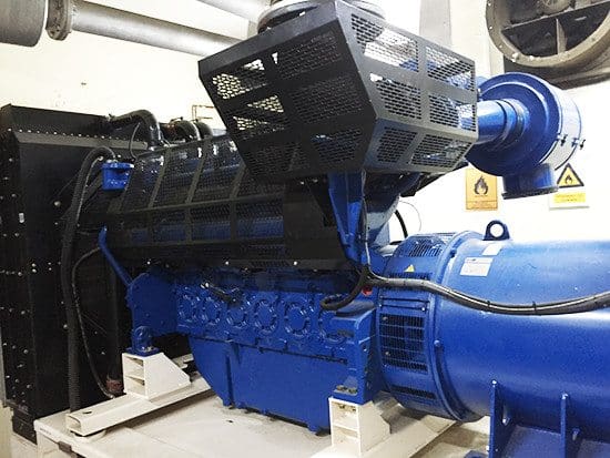
The electrical power supplied by a back-up generator is produced by an alternator, driven by a thermal engine. No power can be produced until the generator has reached its rated speed. This type of device is therefore not suitable for an uninterrupted power supply.

The generator can function permanently or intermittently. Its back-up time depends on the quantity of available fuel. According to the generator’s capacity to supply power to all or only part of the installation, there is either total or partial redundancy.
The implementation of a back-up generator should take consideration of the sensitivity of circuits to power interruptions and the availability of the public distribution network.

Go back to Water Treatment Plants Topics ↑
Presence of Uninterruptible Power Supply (UPS)
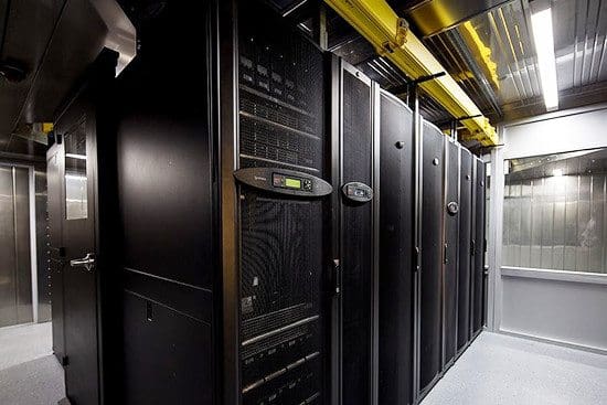
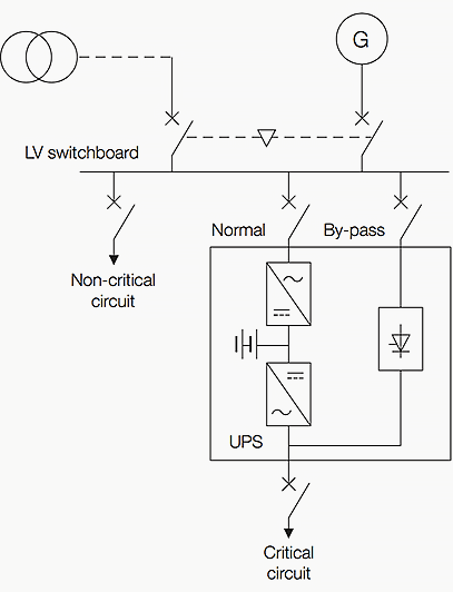
The electrical power from a UPS is supplied from batteries. This system eliminates any power failure. The back-up time of the system is limited: from several minutes to several hours. The simultaneous presence of a back-up generator and a UPS unit is used for permanently supply loads for which no failure is acceptable.
The back-up time of the batteries must be compatible with the maximum time for the generator to start up and be brought on-line.
A UPS unit is also used for supplying power to loads that are sensitive to disturbances (generating a “clean” voltage that is independent of the network).

Main characteristics to be considered for implementing a UPS //
- Sensitivity of loads to power interruptions
- Sensitivity of loads to disturbances.
The presence of a UPS unit is essential if and only if no power failure is acceptable. Generally, process lines in Water applications are not supplied by UPS because of the large power involved and the possibility to accept short interruptions. UPS are necessary only for process control supply.
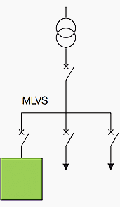
Example of configuration for uninterruptible supply of critical circuit:

Go back to Water Treatment Plants Topics ↑
Guide to Wastewater treatment plants
Recommended electrical network design for efficient plant and energy operations
// by SCHNEIDER ELECTRIC
References //
- Wastewater treatment plants – Recommended electrical network design for efficient plant and energy operations by Schneider Electric
- Water and Wastewater Power Solution Handbook by Schneider Electric




Great professional website. I need new technology update.
I will appreciate if can be receiving update on any Electrical new technology discovery. You are good platform for studying and development.
This was a great read! I can only imagine the cost of the redundancy of the UPS’s and the back-up generators.
Engineer Edvard I want to ask you two things, the first one is: at the single line diagram of autonomous water treatment plant, what does mean the letter “L”?, is this the abbrevaition for Load?. The second question is, why do you refere the words lifting, screening, clarifier, aeration, sludge in the single line diagram?, thanks for your time.
Regards
I read your article and it is very impressive, I m currently work in a power plant located in Venezuela and the water treatment plant uses and osmosis inverse unit and a sulfuric dosage system for the water circulation system. I m electrical engineer but my position in the company is in DCC department, I can review drawings and calculation reports but I can not go to site even to take a picture, I would like to learn more about water treatment plants. By the way, thanks for upload the document from schneider electric.
Regards