PLC installation – input/output
Input/output installation is perhaps the biggest and most critical job when installing a PLC – programmable controller system. To minimize errors and simplify installation, the user should follow predefined guidelines. All of the people involved in installing the controller should receive these I/O system installation guidelines, which should have been prepared during the design phase.
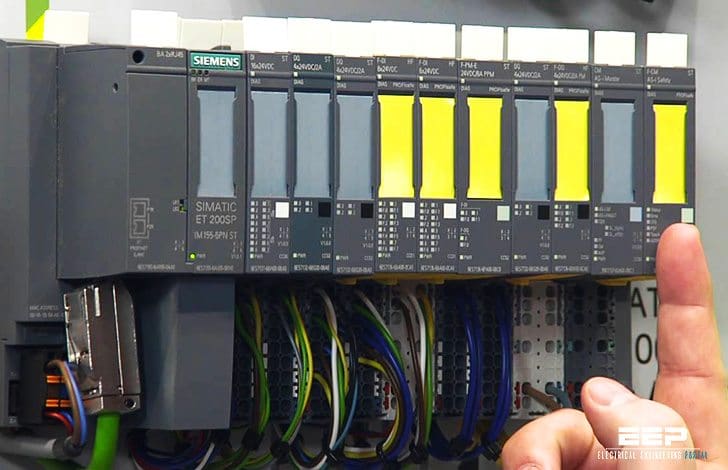
Furthermore, these documents should be constantly updated during every stage of the installation.
The following considerations will facilitate an orderly installation of a PLC:
- PLC I/O module installation
- Wiring considerations
- Recommended wiring procedures
- Wire size
- Wire and terminal labeling
- Wire bundling
- Special I/O connection precautions
I/O module installation
Placement and installation of the I/O modules is simply a matter of inserting the correct modules in their proper locations! This procedure involves verifying the type of module (115 VAC output, 115 VDC input, etc.) and the slot address as defined by the I/O address assignment document. Each terminal in the module is then wired to the field devices that have been assigned to that termination address.
The user should remove power to the modules (or rack) before installing and wiring any module.
Wiring considerations
Wire Size
Each I/O terminal can accept one or more conductors of a particular wire size. The user should check that the wire is the correct gauge and that it is the proper size to handle the maximum possible current.
Wire and Terminal Labeling
Each field wire and its termination point should be labeled using a reliable labeling method. Wires should be labeled with shrink-tubing or tape, while tape or stick-on labels should identify each terminal block. Color coding of similar signal characteristics (e.g., AC: red, DC: blue, common: white, etc.) can be used in addition to wire labeling.
Wire Bundling
Wire bundling is a technique commonly used to simplify the connections to each I/O module. In this method, the wires that will be connected to a single module are bundled, generally using a tie wrap, and then routed through the duct with other bundles of wire with the same signal characteristics.
Input, power, and output bundles carrying the same type of signals should be kept in separate ducts, when possible, to avoid interference.
I/O wiring recommended procedures
Once the I/O modules are in place and their wires have been bundled, the wiring to the modules can begin.
The following are ten recommended procedures for I/O wiring:
- Remove and lock out input power from the controller and I/O before any PLC installation and wiring begins.
- Verify that all modules are in the correct slots. Check module type and model number by inspection and on the I/O wiring diagram. Check the slot location according to the I/O address assignment document.
- Loosen all terminal screws on each I/O module.
- Locate the wire bundle corresponding to each module and route it through the duct to the module location. Identify each of the wires in the bundle and check that they correspond to that particular module.
- Starting with the first module, locate the wire in the bundle that connects to the lowest terminal. At the point where the wire is at a vertical height equal to the termination point, bend the wire at a right angle towards the terminal.
- Cut the wire to a length that extends 1/4 inch past the edge of the terminal screw. Strip approximately 3/8 inch of insulation from the end of the wire. Insert the uninsulated end of the wire under the pressure plate of the terminal and tighten the screw.
- If two or more modules share the same power source, jumper the power wiring from one module to the next.
- If shielded cable is being used, connect only one end to ground, preferably at the rack chassis. This connection will avoid possible ground loops. A ground loop condition exists when two or more electrical paths are created in a ground line or when one or more paths are created in a shield. Leave the other end cut back and unconnected, unless otherwise specified.
- Repeat the wiring procedure for each wire in the bundle until the module wiring is complete.
- After all of the wires are terminated, check for good terminations by gently pulling on each wire.
Special I/O connection precautions
Certain field device wiring connections, however, may need special attention. These connections include leaky inputs, inductive loads, output fusing, and shielded cable.
Connecting leaky inputs
Some field devices have a small leakage current even when they are in the OFF state! Both triac and transistor outputs exhibit this leakage characteristic, although transistor leakage current is much lower.
A typical device that exhibits this leakage situation is a proximity switch. This type of leakage may also occur when an output module drives an input module when there is no other load.
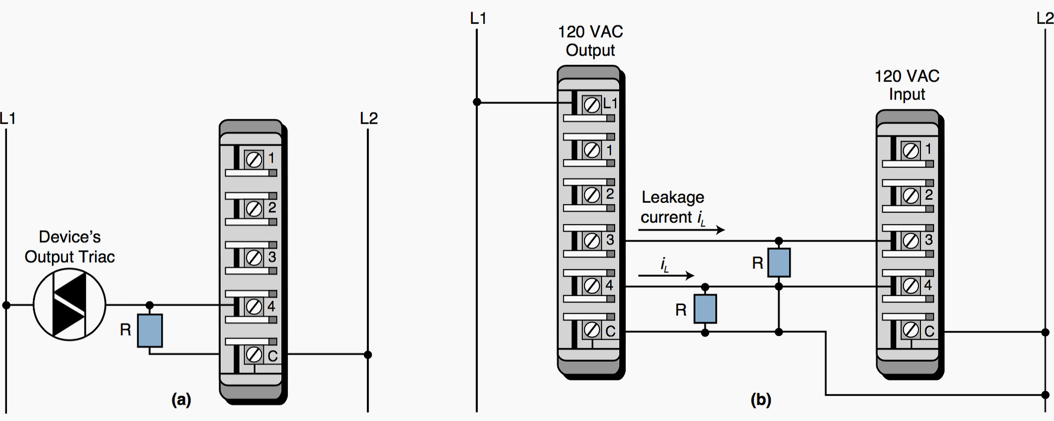

Figure 1 illustrates two leakage situations, along with their corrective actions. A leaky input can be corrected by placing a bleeding (or loading) resistor across the input. A bleeding resistor introduces resistance into the circuit, causing the voltage to drop on the line between the leaky field device and the input circuit. This causes a shunt on the input’s terminals.
Consequently, the leakage current is routed through the bleeding resistor, minimizing the amount of current to the input module (or to the output device). This prevents the input or output from turning ON when it should be OFF.
Suppression of inductive loads
The interruption of current caused by turning an inductive load’s output OFF generates a very high voltage spike. These spikes, which can reach several thousands of volts if not suppressed, can occur either across the leads that feed power to the device or between both power leads and the chassis ground, depending on the physical construction of the device.
This high voltage causes erratic operation and, in some cases, may damage the output module!
To avoid this situation, a snubber circuit, typically a resistor/capacitor network (RC) or metal oxide varistor (MOV), should be installed to limit the voltage spike, as well as control the rate of current change through the inductor (see Figure 2).
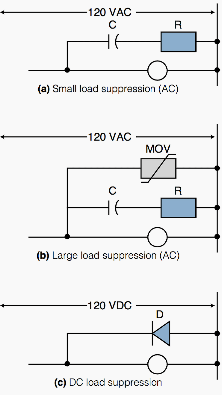

Most output modules are designed to drive inductive loads, so they typically include suppression networks. Nevertheless, under certain loading conditions, the triac may be unable to turn OFF as current passes through zero (commutation), thus requiring additional external suppression in the system.
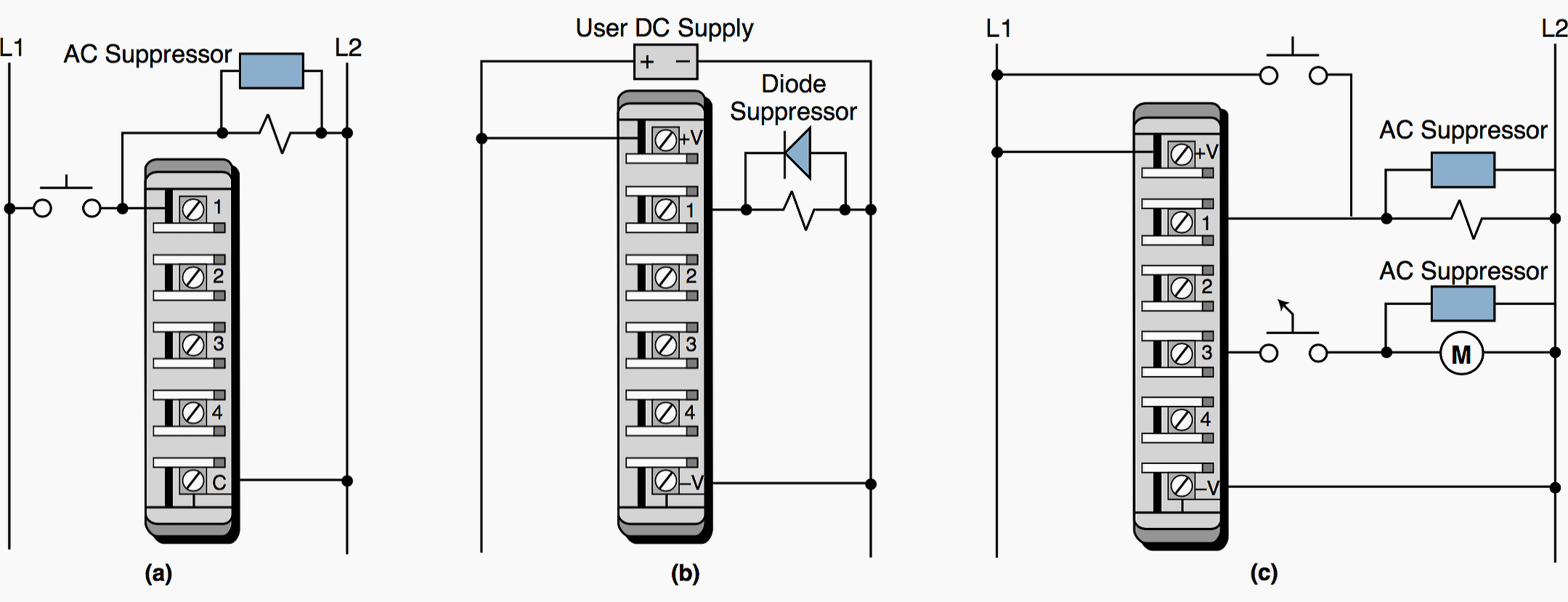
Figure 3 presents several examples of inductive load suppression.

Fusing Outputs
Solid-state outputs normally have fusing on the module, to protect the triac or transistor from moderate overloads. If the output does not have internal fuses, then fuses should be installed externally (normally at the terminal block) during the initial installation.
When adding fuses to an output circuit, the user should adhere to the manufacturer’s specifications for the particular module.
Shielding
Control lines, such as TTL, analog, thermocouple, and other low-level signals, are normally routed in a separate wireway, to reduce the effects of signal coupling. For further protection, shielded cable should be used for the control lines, to protect the low-level signals from electrostatic and magnetic coupling with both lines carrying 60 Hz power and other lines carrying rapidly changing currents.
The twisted, shielded cable should have at least a one-inch lay, or approximately twelve twists per foot, and should be protected on both ends by shrink-tubing or a similar material.


The shield should be connected to control ground at only one point (see Figure 4 above), and shield continuity must be maintained for the entire length of the cable. The shielded cable should also be routed away from high noise areas, as well as insulated over its entire length.
Reference // Programmable controllers: theory and implementation by L.A. Bryan and E.A. Bryan (Purchase hardcopy from Amazon)






thanks
valuable guide to novices and professionals
Can you explain at least 5 manufacturer’s wiring specifications an installations of I/O in PLC?
I am really interested to learn PLC and how to program PLC and field wiring. I am a beginner.
Phases of installation of plc
Please am much interested to learn PLC’s and I need your support in all the hardware wiring systems.
Sharing about plc &HMI can help engineers learn a lot.thank you
Hi, I just wanna ask if what size of wire should I use for the output of the PLC to the Temp. Transmitter, the distance is 176 meters. I recently used 22 AWG shielded type wire, but I think it is too thin for that long distance. Hope you can help me. Thank you.
I have installation where I am using 120 VAC / 24 VDC power supply to supply GE RX3i PLC. PLS is coming with 24 VDC power supply. Do I need to provide protection on 120 VAC / 24 VDC power supply output?
yes we have to provide protection otherwise your plc will go off
You did a very good job of showing a proper quality installation to I/O connections. I have had to repair many installations that did not follow these guidelines and failed because of it. Thank you
THANKS A LOT
Whilst on the topic of panel wiring for PLCs are there standard colours for different wiring categories?
e.g. now that 24Vdc is a control voltage standard what colours should + 24Vdc and 0Vdc?
THANKS