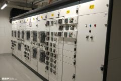
Introduction to PLC/VFD motor control
For the last several decades, every engineering task related to processing control is realized by the use of PLC (Programmable Logic Controller). If we are talking about induction motor control, which is the most common case, usually a VFD (Variable Frequency Drive) is an electrical device placed “between” a PLC and motor, providing a connection of control logic and circuits on one side, with desired power output at the other side.
In that way, these three devices (PLC, VFD and motor), together with field measuring devices, represent one functional whole, capable of control, supply, protection and monitoring of some processes consumer-driven by an induction motor.
In this article, a real example of submersible pump control will be described. Attention will be given to the description of electrical devices, signals, and operation principles.
Example of pump control
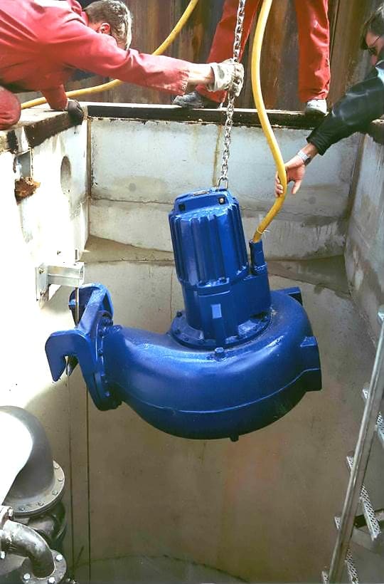
A submersible pump, which is a subject of this example, is used for WWTP (Waste Water Treatment Plant) inlet chamber level control. The physical appearance of this pump type during installation is shown in Figure 1.

Real-time measurement of level is done by ultrasonic level meter placed inside inlet chamber. You can read more about this device in a previous article called “Field devices and signals used for LV SCADA operations”.
This real-time value is transferred to PLC (See Figure 6) and compared to the required level value defined by the operator. Based on the difference between these two values, the required pump flow is calculated using PID control logic. Since pump flow is dependent on pump motor speed (this function is given by pump manufacturer), required flow can be achieved by adjusting a motor speed via VFD which is controlled by PLC.
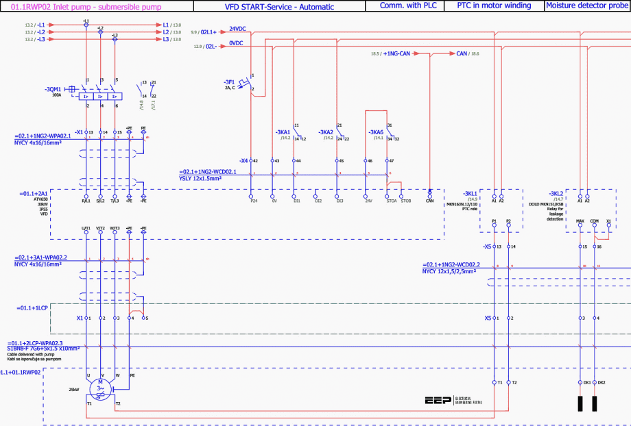
The wiring diagram of VFD outgoing inside MCC (Motor Control Centre) used for pump control is given in Figure 2.


