
Estimated Study Time: 13 minutes
Guidelines to specifying transformers
There are many factors that influence final specification of a transformer. However, the following ten factors MUST be considered when specifying transformers.
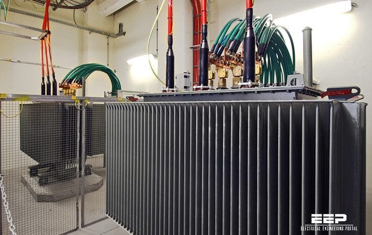 10 Factors To Consider When Specifying Transformers (photo credit: interelectric.co.il)
Let’s name these ten factors:
- Kilovoltampere (kVA) Rating
- Voltage Ratings, Ratio, and Method of Connection (Delta or Wye)
- Voltage Taps
- Typical Impedance Values for Power Transformers
- Insulation Temperature Ratings
- Insulation Classes
- Sound Levels
- Effects of Transformer Failures
- Harmonic Content of Load
- Paralleling transformers
1. Kilovoltampere (kVA) Rating
Table 1 gives the preferred kVA ratings of both single-phase and three-phase transformers according to IEEE C57.12.00-2010, IEEE Standard General Requirements for Liquid-Immersed Distribution, Power, and Regulating Transformers (ANSI).

Go back to Specifying Factors ↑
2. Voltage Ratings, Ratio, and Method of Connection
All the preferred kVA ratings in Table 1 are obviously not available as standard at all voltage ratings and ratios. In general, the smaller sizes apply to lower voltages and the larger sizes to higher voltages.
Voltage ratings and ratios should be selected in accordance with available standard equipment that is indicated in manufacturers’ catalogs. This is recommended, if at all possible, both from the viewpoint of cost and time for initial procurement and for ready replacement, if necessary.
Table 1 – Preferred Kilovoltampere Ratings
| Single-phase [kVA] | Three-phase [kVA] |
| 3 | 9 |
| 5 | 15 |
| 10 | 30 |
| 15 | 45 |
| 25 | 75 |
| 37.5 | 112.5 |
| 50 | 150 |
| 75 | 225 |
| 100 | 300 |
| 167 | 500 |
| 250 | 750 |
| 333 | 1000 |
| 500 | 1500 |
| 833 | 2000 |
| 1250 | 2500 |
| 1667 | 3750 |
| 2500 | 5000 |
| 3333 | 7500 |
| 5000 | 10000 |
Generally, a three-phase transformer secondary voltage should be selected at 480Y/277 V. This has become standard and is compatible with three-phase motors, which are now rated 460 V standard.
Under normal circumstances, a 460 V rating for the transformer secondary should not be selected unless the load is predominantly older motors rated 440 V and located close to the transformer. Phase-to-neutral 277 V circuits can serve fluorescent and high-intensity discharge (HID) lighting.
Go back to Specifying Factors ↑
3. Voltage Taps
Taps are used to change the ratio between the high- and low-voltage windings. Manual de-energized tap changing is usually used to compensate for differences between the transformer ratio and the system nominal voltage. The tap selected in the transformer should be based upon maximum no-load voltage conditions.
For example, a standard transformer rated 13 200 V to 480 V may have four 2.5% taps in the 13 200 V winding (two above and two below 13 200 V). If this transformer is connected to a system whose maximum voltage is 13 530 V, then the 13 530 V to 480 V tap could be used to provide a maximum of 480 V at no-load.
Tap changers are classified as follows //
On-load tap changers
Taps can be changed when the transformer is energized and loaded. These taps are used to compensate for excessive variations in the supply voltage. They are infrequently associated with commercial building transformers except as part of outdoor substations over 5000 kVA.
Load tap changers can be controlled automatically or manually.
No-load tap changers
Taps can be changed only when the transformer is de-energized. Tap leads are brought to an externally operated tap changer with a handle capable of being locked in any tap position. This is a standard accessory on most liquid filled and sealed-type transformers.
On very small liquid filled transformers and most ventilated-dry-type transformers, the taps are changed by moving internal links that are made accessible by a removable panel on the enclosure.
Manually adjustable (handle- or link-operable) taps are suitable for correcting long-term voltage conditions. They are not suitable for correcting short-term (hourly, daily, or weekly) voltage variations.
Automatic tap changing or voltage regulating transformers are relatively expensive so that one of the following solutions might be more appropriate //
- Request improvement of the utility power supply regulation.
- Segregate the circuits so that heavy variable loads are separated from more sensitive loads. When a source transformer constitutes a significant part of the impedance to a sensitive load, use a separate transformer (or secondary-unit substation) for such loads.
- Use voltage regulating supplies for just the sensitive loads.
Go back to Specifying Factors ↑
4. Typical Impedance Values for Power Transformers
Typical impedance values for power transformers are given in Table 2. These values are at the self-cooled transformer kVA ratings and are subject to a tolerance of ±7.5%, as set forth in IEEE C57.12.00-1987 (ANSI).
Non-standard impedances may be specified at a nominally higher cost: Higher impedances to reduce available fault currents or lower impedances to reduce voltage drop under heavy-current, low-power factor surge conditions.
When specifying transformers, best would be to consult manufacturers’ bulletins for impedances of small transformers because they can vary considerably.
Table 2 – Transformer Approximate Impedance Values
| Design impedance (percent) | ||
| High-voltage rating (volts) | Low voltage, rated 480 V | Low voltage, rated 2400 V or higher |
| Power Transformers | ||
| 2400 to 22 900 | 5.75 | 5.5 |
| 26400, 34 400 | 6.0 | 6.0 |
| 43 800 | 6.5 | 6.5 |
| 67 000 | 7.0 | |
| Rated kVA | Design impedance (percent) |
| Secondary-Unit Substation Transformers | |
| 112½ through 225 | Not less than 2 |
| 300 through 500 | Not less than 4.5 |
| Above 500 | 5.75 |
| Network Transformers | |
| 1000 and smaller | 5.0 |
| Above 1000 | 7.0 |
Go back to Specifying Factors ↑
5. Insulation Temperature Ratings
Transformers are manufactured with various insulation material systems (as shown in Table 2).
Performance data with reference to conductor loss and impedances should be referenced to a temperature of 40°C over the rated average conductor temperature rise as measured by resistance.
While Table 3 represents the limiting standard requirements, transformers with lower conductor losses and corresponding lower temperature rises are available, when longer life expectancy and reduced operating costs are desired.
A Class 105 insulation system allows for a 55°C rise with a total ultimate temperature of 105°C. A Class 120 insulation system allows a 65°C rise with a total permissible ultimate temperature of 120°C. An 80°C rise is allowed for a Class 150, a 115°C rise is allowed for a Class 185, and a 150°C rise is allowed for a Class 220. Materials or combinations of materials that may be included in each insulation material class are specified in IEEE C57.12.00-2010 (ANSI).
Table 3 – Insulation Temperature Ratings in °C
| Average conductor temp. rise * °C | Maximum ambient temperature °C | Hot-spot temperature differential * °C | Total permissible ultimate temperature °C | Class of insulation system °C |
| 55 | 40 | 10 | 105 | 105 |
| 65 | 40 | 15 | 120 | 120 |
| 80 | 40 | 30 | 150 | 150 |
| 115 | 40 | 30 | 185 | 185 |
| 150 † | 40 | 30 | 220 | 220 |
* Maximum at continuous rated load.
† Dry-type transformers using a 220°C insulation system can be designed for lower temperature rises (115°C or 80°C) to conserve energy, increase life expectancy, and provide some continuous overload capability.
Go back to Specifying Factors ↑
6. Insulation Classes
Voltage insulation classes and BILs are listed in Table 4.
Table 4 – Voltage Insulation Classes and Dielectric Tests
| Dry transformers | Oil immersed distribution transformers | Oil immersed power transformers | |||||
| Nominal system voltage (kV) | Insulation class | Basic impulse level (kV) | Low- frequency test (kV) | Basic impulse level (kV) | Low- frequency test (kV) | Basic impulse level (kV) | Low- frequency test (kV) |
| 1. | 1.2 | 10 | 4 | 30 | 10 | 45 | 10 |
| 2.4 | 2.5 | 20 | 10 | 45 | 15 | 60 | 15 |
| 4.8 | 5.0 | 30 | 12 | 60 | 19 | 75 | 19 |
| 8.32 | 8.7 | 45 | 19 | 75 | 26 | 95 | 26 |
| 14.4 | 15.0 | 60 | 31 | 95 | 34 | 110 | 34 |
| 23.0 | 25.0 | 110 | 37 | 125 | 40 | 150 | 50 |
| 34.5 | 34.5 | 150 | 50 | 150 | 50 | 200 | 70 |
Go back to Specifying Factors ↑
7. Sound Levels
Permissible sound levels are listed in Tables 5 and 6. Transformer sound levels can be a problem in commercial building interiors, especially where relative quiet is required, such as in conference rooms and certain office areas.
Technical specifications can require transformer sound levels to be below those specified in these two tables.
For large units, providing flexible connections from the transformer to long busway runs will reduce the transmission of vibrations.
Table 5 – Sound Levels for Dry-Type Transformers in dB
| Equivalent two-winding kVA | Self-cooled ventilated [1] | Self-cooled sealed [2] | Forced-air cooled ventilated [3] |
| 0-9 | 45 | 45 | |
| 10-50 | 50 | 50 | |
| 51-150 | 55 | 55 | |
| 151-300 | 58 | 57 | |
| 301-50 | 60 | 59 | |
| 501-700 | 62 | 61 | |
| 701-1000 | 64 | 63 | |
| 1001-1500 | 65 | 64 | |
| 1501-2000 | 66 | 65 | |
| 2001-3000 | 68 | 66 | |
| 3001-4000 | 70 | 68 | |
| 4001-5000 | 71 | 69 | |
| 5001-6000 | 72 | 70 | |
| 6001-7500 | 73 | 71 | |
| 0-1167 | 67 | ||
| 1168-1667 | 68 | ||
| 1668-2000 | 69 | ||
| 2001-3333 | 71 | ||
| 3334-5000 | 73 | ||
| 5001-6667 | 74 | ||
| 6668-8333 | 75 | ||
| 8334-10 000 | 76 |
Columns 1 and 2 — Class AA rating, column 3 — Class FA and AFA rating.
Table 6 – Sound Levels for Single-Phase and Three-Phase Oil Cooled Transformers in dB
| Equivalent two-winding kVA | Without fans | With fans |
| 0-300 | 56 | |
| 301-500 | 58 | |
| 501-700 | 60 | 70 |
| 701-1000 | 62 | 70 |
| 1001-1500 | 63 | 70 |
| 1501-2000 | 64 | 70 |
| 2001-3000 | 65 | 71 |
| 3001-4000 | 66 | 71 |
| 4001-5000 | 67 | 72 |
| 5001-6000 | 68 | 73 |
| 6001-7500 | 69 | 73 |
| 7500-10 000 | 70 | 74 |
Go back to Specifying Factors ↑
8. Effects of Transformer Failures
Transformer failures are rare. However, in high-rise buildings and in other buildings where the conditions for evacuation are limited, the effects of the failure of larger transformers can be serious. Air from transformer vaults should be exhausted directly outdoors.
Well-designed transformer protection can minimize the extent of damage to any type of transformer. Dry-type transformers, including the cast-coil-type, if subjected to faults for an extended period, can burn and generate smoke. Liquid filled transformers can burst, burn, and generate smoke. Provisions can be made for dealing with these rare but still possible failure modes for large transformers in critical areas.
Go back to Specifying Factors ↑
9. Harmonic Content of Load
Very recent developments have indicated failures of certain types of transformers due to nonlinear loads, which cause third and higher harmonics to flow through the windings.
When these harmonics are present, due to loads like computers, variable speed drives, electronic ballasts, HID lighting, arc furnaces, rapid mode switching devices, and similar electrical loads, consideration should be given to specifying a special transformer that is designed to withstand these harmonic currents and the fluxes they produce in the cores.
Go back to Specifying Factors ↑
10. Paralleling transformers
When a transformer is able to be paralleled with another transformer, specifying %IR, %IX, and %IZ is required. Read more about matching transformers for parallel operation.
Go back to Specifying Factors ↑
Reference // Recommended Practice for Electric Power Systems in Commercial Buildings (IEEE STD 241)
Related electrical guides & articles


Edvard Csanyi
Hi, I'm an electrical engineer, programmer and founder of EEP - Electrical Engineering Portal. I worked twelve years at Schneider Electric in the position of technical support for low- and medium-voltage projects and the design of busbar trunking systems.I'm highly specialized in the design of LV/MV switchgear and low-voltage, high-power busbar trunking (<6300A) in substations, commercial buildings and industry facilities. I'm also a professional in AutoCAD programming.
Profile: Edvard Csanyi

Very good article. It is very insightful. Can I get a similar one on electrical motors. Good work.
Per me transformer designer or the person who sign the transformer test report should be Professional engineer License holder of that particular state in which transformer is manufactured and tested. This clause must be added in each specification designed by each utility, which will compel transformer manufacturer to be more liable about their product and stop them to avail and recruit cheap engineer working from remote location who even never seen the transformer and its related issue for the unit they designing by sitting in India and China.
We have a large transformer in our parking lot that is now leaking oil. Our power company had notified us of the problem since the transformer has obviously failed. At the same time, we have had two Trane compressor motors on our roof that have suddenly failed. Our HVAC guy said “they just froze up”…. Now we are wondering if the two events could be related. If so, how can we check before the transformer is disconnected and hauled away? Is there a chance that once the new transformer is in place, it will supply enough power to get out Trane compressors running? Or should we not expect miracles….. Please respond since we are having a real crisis here…. Thank you.
Impedance Temperature Ratings and Voltage Ratings are some of the important things we need to consider in the specifications of a Transformer as they are the basic entities that determines the type of Transformer for our needs and requirements. And to specify a Power Transformer it is also necessary to define the Type of Oil Immersed with or without Conservator or Dry Type Transformer, Type of Installation Indoors, Outdoors, and Pole Mounted, and Pad Mounted, and others. Standards that shall be accomplished, Primary and Secondary Voltages, Vector Group, Cooling Method and built-in Protections, Gas Temperature and Pressure of Oil or Windings Temperature. According to IEC (International Electro-Technical Commission) Standards preferred Rated Power for Medium Voltage / Low Voltage (MV/LV) Transformer are the followings : 25 kVA, 50 kVA, 100 kVA, 125 kVA, 160 kVA, 200 kVA, 250 kVA, 315 kVA, 400 kVA, 500 kVA, 630 kVA, 800 kVA, 1000 kVA, 1250 kVA, 1600 kVA, 2000 kVA, 2500 kVA, to 3000 kVA.
Well Mentioned.
Kindly make your articles pdf to be downloaded.
It could be useful to add data on built-in current transformers as well – in case we have it (quantity, class, current ratio). And data regarding cooling system also.
There are over 130 parameters to completely specify a transformer. Some are very critical. some are not.
This gives a good idea. But I would also add Ambient conditions and Altitude at the location where this transformer will operate.
Excellent article
May we get a pdf file for this topic .
good
Witch Harmonics are produced from Power transformer when it its Not loaded? , then witch Harmonics are produced after loading ?, then how can be solved ?
is it necessary to mention the rates of Harmonics during purchasing power transformer.
excellent articles very good at knowledge base
How should I get the Hard copies of all articl which your forwarding on ELECTRICAL portal continues every week ?
I am intreseted in keeping / stacking in Library.
Impedance Temperature Ratings and Voltage Ratings are some of the important things we need to consider in the specification of a transformer as they are the basic entities that determines the type of transformer for our needs and requirements.
To specify a power transformer it is also necessary to define type (oil immersed – with or without conservator – or dry type), type of installation (indoors; outdoors; pole mounted; pad mounted; etc.), standards that shall be accomplished, primary and secondary voltages, vector group, cooling method and built-on protections (gas, temperature and pressure of oil or windings temperature).
In Europe, according to IEC standards preferred rated power for MV/LV transformers are: 25, 50, 100, 125, 160, 200, 250. 315, 400, 500, 630, 800, 1000, 1250, 1600, 2000 and 2500 kVA.