
Estimated Study Time: 25 minutes
Introduction to Star-Delta Motor Starter
Where is Star-Delta motor starter used? Well, the majority of induction motors are started directly on line (DOL), but when very big motors are started in this manner, the large starting current surges produce a disruption in the voltage on the supply lines. To limit the starting current surge, large induction motors are started at reduced voltage and then have full supply voltage reconnected when they run up to near rotated speed.

Two methods used for reduction of starting voltage are: Star delta starting and Auto transformer starting.
Working Principle of Star-Delta Starter
Star-delta motor start is the reduced voltage starting method. Voltage reduction during star-delta starting is achieved by physically reconfiguring the motor windings as illustrated in the figure below. During starting the motor windings are connected in star configuration and this reduces the voltage across each winding 3.
This also reduces the torque by a factor of three.
After a period of time the winding are reconfigured as delta and the motor runs normally. Star/Delta starters are probably the most common reduced voltage starters. They are used in an attempt to reduce the start current applied to the motor during start as a means of reducing the disturbances and interference on the electrical supply.
Figure 1 – Working Principle of Star-Delta Starter

Traditionally in many supply regions, there has been a requirement to fit a reduced voltage starter on all motors greater than 5HP (4KW). The Star/Delta (or Wye/Delta) starter is one of the lowest cost electromechanical reduced voltage starters that can be applied. [/info_box]
There are two contactors that are close during run, often referred to as the main contractor and the delta contactor. These are AC3 rated at 58% of the current rating of the motor. The third contactor is the star contactor and that only carries star current while the motor is connected in star.
The current in star is one third of the current in delta, so this contactor can be AC3 rated at one third (33%) of the motor rating.
Figure 2 – Star-delta motor starter
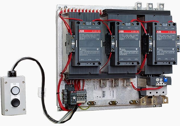
Star-delta Starter Components:
- Contactors (Main, star and delta contactors) 3 No’s (For Open State Starter) or 4 No’s (Close Transient Starter).
- Time relay (pull-in delayed) 1 No.
- Three-pole thermal overcurrent release 1 No.
- Fuse elements or automatic cut-outs for the main circuit 3 Nos.
- Fuse element or automatic cut-out for the control circuit 1No.
Power Circuit of Star Delta Starter
The main circuit breaker serves as the main power supply switch that supplies electricity to the power circuit.
The main contactor connects the reference source voltage R, Y, B to the primary terminal of the motor U1, V1, W1.
In operation, the Main Contactor (KM3) and the Star Contactor (KM1) are closed initially, and then after a period of time, the star contactor is opened, and then the delta contactor (KM2) is closed. The control of the contactors is by the timer (K1T) built into the starter. The Star and Delta are electrically interlocked and preferably mechanically interlocked as well.
Figure 3 – Power circuit of Star-Delta starter

In effect, there are four states:
The star contactor serves to initially short the secondary terminal of the motor U2, V2, W2 for the start sequence during the initial run of the motor from standstill. This provides one third of DOL current to the motor, thus reducing the high inrush current inherent with large capacity motors at startup.
Controlling the interchanging star connection and delta connection of an AC induction motor is achieved by means of a star delta or wye delta control circuit. The control circuit consists of push button switches, auxiliary contacts and a timer.
Control Circuit of Star-Delta Starter (Open Transition)
The ON push button starts the circuit by initially energizing Star Contactor Coil (KM1) of star circuit and Timer Coil (KT) circuit. When Star Contactor Coil (KM1) energized, Star Main and Auxiliary contactor change its position from NO to NC.
When Star Auxiliary Contactor (1) (which is placed on Main Contactor coil circuit ) become NO to NC it’s complete The Circuit of Main contactor Coil (KM3) so Main Contactor Coil energized and Main Contactor’s Main and Auxiliary Contactor Change its Position from NO to NC. This sequence happens in a friction of time.
After pushing the ON push button switch, the auxiliary contact of the main contactor coil (2) which is connected in parallel across the ON push button will become NO to NC, thereby providing a latch to hold the main contactor coil activated which eventually maintains the control circuit active even after releasing the ON push button switch.
When Star Main Contactor (KM1) close its connect Motor connects on STAR and it’s connected in STAR until Time Delay Auxiliary contact KT (3) become NC to NO.
Once the time delay is reached its specified Time, the timer’s auxiliary contacts (KT)(3) in Star Coil circuit will change its position from NC to NO and at the Same Time Auxiliary contactor (KT) in Delta Coil Circuit(4) change its Position from NO To NC so Delta coil energized and Delta Main Contactor becomes NO To NC. Now Motor terminal connection change from star to delta connection.
Figure 4 – Control Circuit Scheme of Star-Delta Starter (Open Transition)
")
A normally close auxiliary contact from both star and delta contactors (5&6) are also placed opposite of both star and delta contactor coils, these interlock contacts serves as safety switches to prevent simultaneous activation of both star and delta contactor coils, so that one cannot be activated without the other deactivated first.
Thus, the delta contactor coil cannot be active when the star contactor coil is active, and similarly, the star contactor coil cannot also be active while the delta contactor coil is active.
At some point during starting it is necessary to change from a star connected winding to a delta connected winding. Power and control circuits can be arranged to this in one of two ways – open transition or closed transition.
What is Open or Closed Transition Starting?
1. Open Transition Starters
Discuss mentioned above is called open transition switching because there is an open state between the star state and the delta state. In open transition the power is disconnected from the motor while the winding are reconfigured via external switching. When a motor is driven by the supply, either at full speed or at part speed, there is a rotating magnetic field in the stator. This field is rotating at line frequency. The flux from the stator field induces a current in the rotor and this in turn results in a rotor magnetic field.
When the motor is disconnected from the supply (open transition) there is a spinning rotor within the stator and the rotor has a magnetic field.
Due to the low impedance of the rotor circuit, the time constant is quite long and the action of the spinning rotor field within the stator is that of a generator which generates voltage at a frequency determined by the speed of the rotor.
Open transition starting is the easiest to implement in terms or cost and circuitry and if the timing of the changeover is good, this method can work well. In practice though it is difficult to set the necessary timing to operate correctly and disconnection/reconnection of the supply can cause significant voltage/current transients.
In open transition there are four states:
- OFF State: All Contactors are open.
- Star State: The Main [KM3] and the Star [KM1] contactors are closed and the delta [KM2] contactor is open. The motor is connected in star and will produce one third of DOL torque at one third of DOL current.
- Open State: This type of operation is called open transition switching because there is an open state between the star state and the delta state. The Main contractor is closed and the Delta and Star contactors are open. There is voltage on one end of the motor windings, but the other end is open so no current can flow. The motor has a spinning rotor and behaves like a generator.
- Delta State: The Main and the Delta contactors are closed. The Star contactor is open. The motor is connected to full line voltage and full power and torque are available
Watch Video – Wye(Star)-Delta Closed Transition Starter using FluidSim v3.6
Here is a control system for the starter wye-delta in a closed transition. If you want to do the Control System please make sure that the label of the Contactor and its Coil is the same for it to act simultaneously with respect to when the Contactor Coil is energized. You can label it by double clicking and type the desired label for it. Also, make sure the Contactors if it’s Normally Open or Closed.
I also made an artificial three phase connection to illustrate the current flow. It is only for aesthetic purposes. In order for it to work, I series a lamp for every line to avoid short circuiting.
Take Note: Focusing in the artificial three-phase windings, the current flow in the artificial winding looks like it’s not in closed transition but the Control System is on a closed transition set-up.
2. Closed Transition Star/Delta Starter
There is a technique to reduce the magnitude of the switching transients. This requires the use of a fourth contactor and a set of three resistors. The resistors must be sized such that considerable current is able to flow in the motor windings while they are in circuit.
The auxiliary contactor and resistors are connected across the delta contactor. In operation, just before the star contactor opens, the auxiliary contactor closes resulting in current flow via the resistors into the star connection. Once the star contactor opens, current is able to flow round through the motor windings to the supply via the resistors. These resistors are then shorted by the delta contactor.
If the resistance of the resistors is too high, they will not swamp the voltage generated by the motor and will serve no purpose.
These resistors need to be sized to carry the motor current. In addition to requiring more switching devices, the control circuit is more complicated due to the need to carry out resistor switching
In close transition there are four states:
- OFF State: All Contactors are open.
- Star State: The Main [KM3] and the Star [KM1] contactors are closed and the delta [KM2] contactor is open. The motor is connected in star and will produce one third of DOL torque at one third of DOL current.
- Star Transition State: The motor is connected in star and the resistors are connected across the delta contactor via the aux [KM4] contactor.
- Closed Transition State: The Main [KM3] contactor is closed and the Delta [KM2] and Star [KM1] contactors are open. Current flows through the motor windings and the transition resistors via KM4.
- Delta State: The Main and the Delta contactors are closed. The transition resistors are shorted out. The Star contactor is open. The motor is connected to full line voltage and full power and torque are available.
Effect of Transient in Starter (Open Transient starter)
It is Important the pause between star contactor switch off and Delta contactor switch is on correct. This is because Star contactor must be reliably disconnected before Delta contactor is activated. It is also important that the switch over pause is not too long.
For 415 V Star Connection voltage is effectively reduced to 58% or 240 V. The equivalent of 33% that is obtained with Direct Online (DOL) starting. If Star connection has sufficient torque to run up to 75% or 80% of full load speed, then the motor can be connected in Delta mode.
When connected to Delta configuration the phase voltage increases by a ratio of V3 or 173%. The phase currents increase by the same ratio. The line current increases three times its value in star connection.
During transition period of switchover the motor must be free running with little deceleration. While this is happening “Coasting” it may generate a voltage of its own, and on connection to the supply this voltage can randomly add to or subtract from the applied line voltage. This is known as transient current. Only lasting a few milliseconds it causes voltage surges and spikes. Known as a changeover transient.
Sizing Star-Delta Starter Components
1. Size of Over Load Relay
For a star-delta starter there is a possibility to place the overload protection in two positions, in the line or in the windings.
Overload Relay in Line:
In the line is the same as just putting the overload before the motor as with a DOL starter. The rating of Overload (In Line) = FLC of Motor.
Disadvantage: If the overload is set to FLC, then it is not protecting the motor while it is in delta (setting is × 1.732 too high).
Overload Relay in Winding:
In the windings means that the overload is placed after the point where the wiring to the contactors are split into main and delta. The overload then always measures the current inside the windings.
The setting of Overload Relay (In Winding) =0.58 X FLC (line current).
Disadvantage: We must use separate short circuit and overload protections.
2. Size of Main and Delta Contactor
There are two contactors that are close during run, often referred to as the main contractor and the delta contactor. These are AC3 rated at 58% of the current rating of the motor.
Size of Main Contactor = IFL × 0.58
3. Size of Star Contractor
The third contactor is the star contactor and that only carries star current while the motor is connected in star. The current in star is 1/ √3= (58%) of the current in delta, so this contactor can be AC3 rated at one third (33%) of the motor rating.
Size of Star Contactor= IFL × 0.33
Watch Video – Wye Delta Starter Demo
Here is a quick demo of a Wye Delta motor starter in action. They can also be called Star Delta Starters.
Motor Starting Characteristics of Star-Delta Starter
- Available starting current: 33% Full Load Current.
- Peak starting current: 1.3 to 2.6 Full Load Current.
- Peak starting torque: 33% Full Load Torque.
Advantages of Star-Delta starter
The operation of the star-delta method is simple and rugged. It is relatively cheap compared to other reduced voltage methods. It has a good Torque/Current Performance and it draws 2 times starting current of the full load ampere of the motor connected
Disadvantages of Star-Delta starter
- Low Starting Torque because Torque = (Square of Voltage) is also reduced.
- Break In Supply – Possible Transients.
- Six Terminal Motor Required (Delta Connected).
- It requires 2 set of cables from starter to motor.
- It provides only 33% starting torque and if the load connected to the subject motor requires higher starting torque at the time of starting than very heavy transients and stresses are produced while changing from star to delta connections, and because of these transients and stresses many electrical and mechanical break-down occurs.
- In this method of starting initially motor is connected in star and then after change over the motor is connected in delta. The delta of motor is formed in starter and not on motor terminals.
- High transmission and current peaks: When starting up pumps and fans for example, the load torque is low at the beginning of the start and increases with the square of the speed. When reaching approx. 80-85 % of the motor rated speed the load torque is equal to the motor torque and the acceleration ceases.To reach the rated speed, a switch over to delta position is necessary, and this will very often result in high transmission and current peaks. In some cases the current peak can reach a value that is even bigger than for a D.O.L start.
- Applications with a load torque higher than 50 % of the motor rated torque will not be able to start using the start-delta starter.
- Low Starting Torque: The star-delta (wye-delta) starting method controls whether the lead connections from the motor are configured in a star or delta electrical connection.The initial connection should be in the star pattern that results in a reduction of the line voltage by a factor of 1/√3 (57.7%) to the motor and the current is reduced to 1/3 of the current at full voltage, but the starting torque is also reduced 1/3 to 1/5 of the DOL starting torque.
- The transition from star to delta transition usually occurs once nominal speed is reached, but is sometimes performed as low as 50% of nominal speed which make transient Sparks.
Features of star-delta starting
- For low- to high-power three-phase motors.
- Reduced starting current
- Six connection cables
- Reduced starting torque
- Current peak on changeover from star to delta
- Mechanical load on changeover from star to delta
Application of Star-Delta Starter
The star-delta method is usually only applied to low to medium voltage and light starting Torque motors. The received starting current is about 30 % of the starting current during direct on line start and the starting torque is reduced to about 25 % of the torque available at a D.O.L start. This starting method only works when the application is light loaded during the start.
If the motor is too heavily loaded, there will not be enough torque to accelerate the motor up to speed before switching over to the delta position.
Suggested Course – Motor Control Schematics Course For True Engineers
Related electrical guides & articles


Jignesh Parmar
Electrical Middle management professional having more than 22 years rich and dynamic experience in Project Execution / Project Management / Designing / Maintenance diversifies from Electrical Power Transmission (400KV/220KV/66KV)- Distribution(11KV/220V) to Lifts-HVAC-Ventilation-Fire Fighting-Fire Alarm-Lifts-CCTV-Stack Parking Works (High Rise Buildings, Townships, Shopping Complex, Commercial Complex, School, Temple).Profile: Jignesh Parmar

this is a needed library of knowledge, thanks
There is a mistake in start delta wiring drawing.
There are two major flaws:
1. main contactor outgoing phase R to U1, Y to V1 , B to W1 are correct . But the delta contactor outgoing phase R to W2, Y to V2 , B to U2 are WRONG. Should be R to V2, Y to W2, B to U2 , for CW direction of rotation.
2. Usually the thermal over-load relay is not placed at the incoming, which would have to be rated for the full load current. Most manufacturers place the thermal over-load relay at the main contactor outgoing terminal. This is rated to 0.85 of full-load current.
Che Kuan Yau (Singapore)
As per theory I have read,your star delta configuration is wrong… But my elder brother who makes electrical panel for injection die casting machine, creats circuits, as you have design….
Is there something, we regular persons do know, but experience engineers do…
Theory is different from practical?
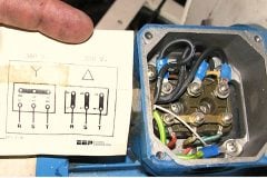
Motor terminal sequence in all the 6 terminal motors as below
U1 V1 W1
V2 W2 U2
So his nomenclature for u2v2w2 is wrong, but if he no his wires as in practice, connection would be correct. That’s why your brother’s wiring get correct output.
U1 V1 WI
W2 U2 V2 is also right
Your star delta power wiring connection is wrong
Which is v1 and v2 you are connected in same phase . Please correct the pic
Thanks
ver nice description
good explanations
Although the star delta starter wiring diagram is very helpful and easy to read. It isn’t quite correct. On the delta contactor side you have W2,V2,U2 going to the motor. Which means V2 and V1, will end up being on the same phase in delta. It should read, W2,U2,V2.
Very nice lecture that you do not thought in the schools, thanks
Electric motor 90 KW power rated, 4.16 KV voltage rated ; does it need star delta starter for starting or direct on line could be connected?
Hello Mr. Jignesh,
I have a few question regarding three-phase AC motor. I hope you can help me to solve these questions below.
1) How do we calculate the rating of thermal overload relay needed to start a 3 HP motor by using D.O.L method?
2) Can we run a 3 HP by supplying a 12 VDC to the control circuit? Why?
3) How do we calculate the rating of thermal overload relay to start a 15 HP motor by using STAR-DELTA method?
Regards,
Que Hatt
Star delta starter 248a ,150kilowatt motor Overload capacity 110% for 60seconds ,165% for 4 seconds and output frequency 0-250 hz
Must the KW of the contactor be the same as the KW of the motor?
True. The connections on the motor are not correct
İch bedanke mich sehr für diese erklärung . İch finde diese artikel sehr schön , können sie bitte mehrere dinge erklären ? Und die obere fragen antworten
Interesting work
Hi just a heads up that U2 and V2 should be reversed because the way it is shown, in Delta run U1 and U2 are connected together which cannot work.
The way it is shown, delta connection is U1-W2, V1-V2 and W1-U2
The way it should be is: U1-W2, V1-U2 and W1-V2
Hello,would you mind if I asking the difference between two model below
1.main contactor_star_delta
2.star-main contactor-delta
Sincerely
Please can i have the clear control line diagram of a star delta starter sent to my email? If yes please kindly send it to me. Thank you
Sir, I have one doubt, why do we use 2 NO auxiliary contact of the main contactor in two different places.
Initially, when you press the start button Contact (1) Start Aux contact changes its state to NC to energize the main contractor. After that, NO contact (2) main aux contact changes its state to hold it.
Because you want to interlock the contactors and be able to work simultaneously.
Hello, the power wiring diagram of above connection is mismatched.
Connection of v2 and w2 of power wiring should be in reverse order.
Dear Sir
We supply motors with Delta connection for 0.75 kw and the peak current is 600% (in terms of full load) as per standard,if it is connected in star connection what is the peak current percentage allowd for a 4 pole 0.75 kw motor
Thanks for the lengthy expansion on the full details of Star Delta configuration.
Is there any difference between Star connected motor and Deltal connected motor?
Nice article. Can the motor be wired to delta configuration only (run winding) instead of start? And just use one motor contact?
I want to teach me how to install electricity
Hi I’m having a intermittent fault with star delta, I can switch it on and 3 or 4 times and then there’s a short sometime s when I start it or whilst in delta but with the motor cables disconnected and it actually damages the main breaker could you please help
Dear sir, is star delta starter good for smooth start of 7.5 hp 3 phase motor to prevent wear and tear. Pls reply asap. Thanking you.
I also want to know more about delta star connection of motors
Greetings, regarding the transients that are generated in the transition time between star to triangle, how effective are the special use star / triangle timers that give a small delay time to the period between the change from star to triangle.
We need timing function removing from starter
Sir,
If we connect Main contactor first instead of Star contactor, what will be the consequences.
Thanks a lot sir, this ur article is profitable to me. Pls., I observed that your Y/Delta drawing is incorrect, see: the motor secondary terminal V2 will be returned to the primary terminal V1 whenever the delta contactor energizes & this isolates this winding out of the other 2windings of the 3phase motor. If, my observation is wrong/true pls give me a feedback. Thanks sir.
yes you are right OKORIE UCHENNA EPHRAIM.
I notice that v1 and v2 shouldn’t connect together .
Your S/D Power drawing is incorrect, if you check it !!!
To know more about industrial automation
Hi i want t know about the panels used in industry especially the mcc’s and the one in the power house for the distribution
thanks for your explanation
it is a precise explanation
Dear Sir
Please suggest us regarding 60Hp/4p motor application centrifugal fan. setting for relay and timer.
We are facing the problem with our FD fan of 55 KW for boiler operation – Delta contactor is being stuccked during normal running of the FD fan.
Pl suggest / guide.
regards,
Contactor rating
Thanks so much for the knowledge you impacted online and during your stay at the LEC.
still looking forward to more.
Sir there is power connection error between main contactor and delta contactor which will cause tripping of contactor when is shifting from star to delta connection.it will start just fine because star contactor power lines are connected in parallel but when switching to delta will just trip because in delta phase are connected in series.
wanted to know how to come up with star delta starter with timer
I would like to request a Forward-Reverse Star-Delta operation
There is a big mistake (an error) in the above power circuit of star-delta. Where Live R is connected between U1 and W2(Its right). Live Y is connected between V1 and V2 (which is wrong). Live Y should be connected between V1 and U2). Live B is connected between W1 and U2 (which is wrong). Live B should be connected between W1 and V2
Please sir,I want to know more on star- delta connection and on line connection
In auto Star-delta starter, when star contractor hold motor running but when delta contractor hold motor not run and contractor hold proper,
Hi sir I like to ask about KM1 function in single phase motor
Thanks for your information.,,
very usefull,,
Disadvantage: If the overload is set to FLC, then it is not protecting the motor while it is in delta (setting is x1.732 too high).
I’m not able to understand the why the OLR will not take care the current on delta run. How ever the total current will flow through the OLR contacts
Overload Relay in Line:
Disadvantage: If the overload is set to FLC, then it is not protecting the motor while it is in delta (setting is x1.732 too high).
I’m not able to understand the why the OLR will not take care the current on delta run. How ever the total current will flow through the OLR contacts
I have e-motor 7.5 hp driver driving 10 kw AC alternator, what value of mc should I use and model of the timer and o.l. kindly send to me a proper diagram of control circuit and power circuit, I am novice electrician.
Dear sir
Star delta power cricket is wrong
Sir, This is regarding the 3 phase squirrel cage induction motor of 400/440 V, 3 phase, 50Hz, AC, 1500rpm, 200HP motor, During starting it is fine but when it changes from Star to Delta, the said motor gets tripped. So in this view i would like to seek your good advice to move way forward.
Hope you will help me.
I’m having a problem that the circuit breaker protecting the circuit trips when the delta contactor is energized. Why does the circuit breaker protecting the circuit trips when the delta contactor is energized? Cause in star it didn’t. I did replace the breaker since it was defective and it ran for a couple of days, but I’m back at square one since it’s tripping again.
In this case, your delta connection(Output) wrong phase. Changed the phase sequence. Hope it will be solved. Thanks.
When switch star to delta (low to high load ) any specific time need?
When switch star to delta (low to high load ) any specific time need? Specially in 15 Ho moter
the base line for timer setting is around 10 until 20 seconds
GOOD DAY ,BOSS ,MADAAM
YOU HAVE CONTROL SYSTEM THRU BLUE TOOTH OR REMOTE SYSTEM CONTROL WITD 20 METER RANGE. DUE TO UNDERLINE POWER SUPPLY FOR SAFETY REASON BOSS,MADAAM.
THANK YOU AND MORE POWER.
Hi
Greetings!
I would like to know about the selection of cable for motors. As the starting current is very high and if we select the cable on full load amps so can it bear the high inrush current? Kindly let me know.
Thanks & Regards,
Syed Shahbaz Hussain
Reply
In the diagram of Power Circuit of Star Delta Starter, U2 and V2 of 3 phase motor should be connect to 4 and 6 respectively instead of U2 and V2 are connected to 6 and 4 of Delta Contector KM2.
There is minor correction is require to change (printed in boxes) sequence of 3 phase wires from W2 V2 U2 to W2 U2 V2 to get Delta connection properly.
Please check my comment by qualified person because I am not in electrical line.
Hi Shahbaz,
In-rush current time duration is very low. If you looked at the power dissipation over time, it does not carry enough energy to create significant heat generation through I^2R losses due to the thermal inertia of the Cu/Al material. To size a cable for 6 times the nominal load current would be a massive waste of resources and money.
Dear Sir
We are using 75kw @ 2pole motor for our fire fighting pump, but during start at star circuit we measured its load reached 170ampere, and during delta ampere drops to 80ampere
please comment
I HAVE A STAR DELTA STARTER FOR 5.5KW MOTOR ,ITS MCB HAVE A RATING OF 32A ,BUT DURING STAR TO DELTA TRANSITION MY MCB TRIPS, WHILE I RUN THE SAME MOTOR BY A VFD THEN MCB IS NOT TRIPPING, PLS EXPLAIN WHY TRIPPING OF MCB OCCURS ?
the star delta stater has correct voltage and frequency to main and auxiliary circuits.when the start button is operated a single contactor is hard to operate, but the motor does not run.whent the start button is released,a contactor is heard to move again?
Hi I have a 75 hp motor 1475 rpm what size star delta starter should I use and the size of over load relay. What would be the max amps
of the motor under full load
Dear Sir,
One of the best Knowledge and True information i have got.
Thank you.
But I have to size the transition resistor for the star-delta closed transition starter of a ID fan motor of 160kW, 400V, 50Hz, 4 poles.
Please provide me with the value of resistances (ohms) and power (Watts).
Thank you
hai sir i need a ppt about star-delta starter couid you please send it to my gmail please sir it is urgent
One of the best Knowledge and True information i have got.
Thank you.
In a star-delta connection, does the speed change when the the motor change from Star over to Delta?
Thank you for the details..
The diagram is wrong..
the motor terminal should be UVW VWU or UVW WUV.
UVW WVU is wrong.
Thnak you,
Jafar
Will u please send the correct diagram to my mail
hii sr i need ats pannal coontrol diagram can you some help me…?
Star delta used upto how many hp of motors
sir,
IFL -stands for what ,
FLC -full load current
Inial Full load
Full load current
Dear Jignesh,
Hi!
Is there any solution for the contactor stucking of 55KW or 260KW motor in star delta starter, these motors are running very high torque. Due to conntactor stucking many timer motor winding burnt.
So pl do the needful.
regards,
Ravindra
Hi Sir,
thanks for the information.
I got a burn accident in the motor rewinding because the missing interlock between delta contactor with the main contactor.
The delta was stuck mechanically while the main is closed!
If interlock the main (KM3) with delta (KM2) could solve the problem, but there will be a millisecond open in the Main contactor during the changeover.
Is this correct?
the milisecondes open in the main contactor during the changeover could cause any problem?
Hi all,
i am need of a generator for irrigation application,(2 individual 10 HP pump sets)
with inquiry i came to know the capacity required will be 40KVA !!
and they quoted for 2.4 lakhs, please suggest for the wayforward
Dear Sir,
We are Trading Company in Sri Lanka and doing Tender business with Govt Institution.
We need the 2 Nos Star Delta Compete Box HP25 (18.6 ww)
Please send the your price with delivery period.
and Model Number and country of origin
What is the roll of timer.without timer what affect in starters
The page before was better because it allowed copying or downloading what I published in PDF now and only lets print it bad that bad serivicio. I was better before.
circuit confuse me i think its a wrong circuit plz recorect or remove it…thanks
yes its wrong..really confused the hell out of me . its wrong
Circuit is wrong. Please correct it or remove the diagram.
Very informative. appreciate the explanation.
Hi,
Please tell me where is the normal phase , neutral & Motor phase can be found in the star delta starter
I want to connect a simple circuit which need these 3 as input to it , so kindly help me in finding
Regards
Hizam
Dear Sir/Madam,
In the star delta diagram it is giving the impression that the V1 and V2 will be connected together when in delta configuration.
Regards
Franklyn Linley
THE STAR DELTA STARTER DIAGRAM IS WRONG(Diagram with heading star delta starter and bottom power circuit of star delta starter).THE V1 AND V2 END OF WINDING CONNECTED TO SAME PHASE OR IN OTHER WORD SHORTED.
What is the rating of MCCB for the branch circuit in terms of motor Full load current (FLA) when the starter is star delta ?
Can we use 200%FLA for the MCCB rating as the starting current during wye delta starting will be less than that of the starting current compared with a DOL starter?
(NEC 430.52 table suggest the short circuit protective device to be less than 250%FLA for inverse time breaker.)
Please explain. Thank you.
sir,
what meaning of 240 delta/ 415 v star connection , please give me answer what its says ,
can motor run on delta or run on star,
hi plz help me i neet to draw schema of startup delta-star for a water pump (75KW)
Hi.
How can I do a power factor correction in a star-delta motor starter?
Thank you
Thank you for great article.
Please double check location of overload relay
line current -> between MCCB and MC
Phase current -> between MC and Motor
Hi,
what would be the safest location of an OL relay, inline or in winding?
Can you make a video or lecture on how to connect the motor control circuit let’s say DOL/forward reverse/wye-delta in the motor connection box having 3 leads/6 leads/etc.
Because I,ve known how to make control but then it confuses me on how to connect the 3 wires (3Ø) coming from the overload relay into the motor terminal leads.
Thanks,
I’ll be waiting for your response..
Good,but carefully marked cable correctly as in V2,W2.
Please can you provide or quote for me the iee reg regarding KW rating that a motor can be started on star delta
Motor connection is wrong please modify
Great mind,thanks for the lesson.
Hi. I have a submersible induction Motor 30kW, this motor at no-load test started normally on star connection and during delta transition supply protection circuit breaker is tripping.
please help me…
thank you
check the way u Delta-ed your motor, either you identified wrongly one of your winding beginning and end
on full load running condition in delta what load become if one resistance break?
Dear sir
in our organisation one problem is facing while using star delta starter for 165kw motor having 391FLA. It has two alternatives one is vfd and other is STA/DELTA starter switching. now drive is in trouble we tried to switching the motor with star delta starter but it is tripping continuously. the motor is using for induced draft fan. we closed all the dampers and started the motor with STAR/DELTA starter by setting the star time as 9SEC anf relay set point 390A and PAUSE TIME 90mili SEC. star delta formation is correct and while tripping the currents taken minimum 715A in STAR and then shifted to delta it was tripping with overload.can u suggest me about star timing with formula and if it have to be run in closed transition please send me the power and control diagram with resistor calculation formula. i am having more interest about learing of these things
The ID fan is a high inertia load which it takes considerable time to accelerate to full speed. In such condition, if star to delta switching is done before fan/motor achieves at least 80% of rated speed, this type of problem of tripping on overload occurs. The remedy lies in increasing star to delta change over time, but how much is the question. The practical approach is to work out the time by running the drive in star condition with timer control disconnected (so that star to delta change over does not occur for this experimental run). The time by which motor accelerates to full speed (which can be observed by pointer of Analog Ammeter connected) is the time of star to delta change over. If this time is too long (say more than 45 sec.) either VFD is recommended or higher HP/KW motor is recommended
good idea thank u a lot
It seems that the connection of star delta contactor diagram above has a mistake, v2 and w2 were wrongly marked.
Good for all
good information but some confusing if recorrected its better
I have gone through this basic article. It’s informative for the beginners. A correction needs to be made in power circuit wiring I.e. When delta contacter is energised U2 terminal must be connected to V1 terminal and V2 terminal must be connected to W1 of motor windings. Hope the writer shall agree.
Am very grateful for the clear information and drawings, my pleasure.
thanks u very much, i like the drawing traced in the website which is clear and detail drg. waitig in the future every electrical drawings/diagrams to get in my e-mail address. especially I need wiring ckt diagram of an ATS systems generator to line connection diagram, 2) controlling (managing) system of multi killo watt hour meters by one generator out put with out any interaption power.
Very good information. .
Thank you
Eng. Ayoub
The v1/v2 winding in your diagram is connected to the same phase. This I think is incorrect as it needs to be connected across two different phases.
Thanks for bringing this up.
I was looking at this article to confirm the idea after designing my own star/delta switch… the common V1/V2 in delta mode in this diagram was confessing the hell out of me. I asked elsewhere…
Is there a correct way to switch to delta and maintain same direction of rotation… Its seems just as valid to me to connect U1/W2, W1/Y2, Y1/U2 or U1/Y2, Y1/W2, W1/U2… but i can’t get my head around if this will affect direction of rotation and if so, which way will maintain the direction of the original star connection??? Thanks
Can you guys please try and introduce a section whereby a drawing can also be accompanied by images
sir, can you please explain how to find out star and delta connection in motor
Thank you for the information.
upto how many kilowatts using star delta starter
please explain control circuit for star delta starter without timer.
selection of olr for 25 hp star delta starter
Which OLR range I should use?
Dear Sir,
As per your given Fig. (Scheme – Control Circuit of Star-Delta Starter (Open Transition)).
When the supply will on only timer coil energized But not pick up Main contact whenever it not get supply.
as per my knowledge you have to interchange timer coil & main contactor coil idealy.
Ideally process as per below.
1) Start Push Button press
2) Main contactor coil get supply & change it contact.
3) Main supply will goes through to this contact
4) another main contactor contact will supply current to timer coil.
5) that time Star contactor coil get supply it will open delta contactor line.
6) after specific time Timer Contact change it will give supply to DELTA contactor.
7) When DELTA contactor get supply its contact will be change & open the STAR contactor line.
In your system There is One more STAR contact required for supply main contactor.
which ideally is not necessary.
You are right Dhval!
Hi there,
We need to install variable speed drive for 1x75kW Teco motor and 1x 160kW Teco motor at our Station. Currently the motors run using Star Delta. We will install VSD system for these two motors. When there is a need, we can swap from star Delta to VSD. We would like to check if using VSD will cause any damages to the motors.
how can you know this is the u terminal of primary windind of the motor from the v and w terminal
Its simple… Just check the continuity of terminals with help of multi meter.
good..
thanks mayank barot
u r a teacher indeed. A news letter once in a while is not bad.
Ur page is thorough. u r a teacher. thanks
hello sir, we design electrical control panel boards for rice industries. We presently worked on Asia’s #1 rice industry using programmable logic control. I need some more ideas which are newer and simpler to work. Can u please guide us.
Good
Excellent articles
received good response about any technical item that was written to you for answer.
Nice piece. Send me your Newsletters pls.
Dear sir,
Thank you for explaining it so beautifully that almost covered my doubts but Does FLC stands for full load current and what does IFL stands for.
Sorry for asking immature questions.
Thanking you
Manish.
The “Power Circuit” in the above article has a flaw in it. In the way the motor are now connected, the “Yellow” (Y) supply phase is connected on both sides of the “V” winding resulting in no voltage over that specific winding. Therefore the motor will not run but would trip the overload (or even worse if the overload is faulty or oversized, the motor would burn) because the motor is in effect “two phasing”.
In the drawing in the article above If we leave the “line side” of the main and delta contactors wiring as it currently are, then we need to swap around some “motor cables” on the “motor side” of the main and delta contactors to correct the error. How we swap them around depends on what rotation we need from the motor, “Forward” (also known as clockwise) or “Reverse” Reverse (also known as counter clockwise) rotation.
The correct way to wire for Forward (also known as clockwise) rotation we need to wire as follows:
Main set contacts from left to right (terminals 2—4—6): U1—V1—-W1
Delta set contacts from left to right (terminals 2— 4—6): V2—W2—-U2
For Reverse (also known as counter-clockwise) rotation we need to wire as follows:
Main set contacts from left to right (terminals 2— 4—6): V1—U1—-W1
Delta set contacts from left to right (terminals 2— 4—6): U2—W2—-V2
This method of connecting is the correct way to connect the motor to the “Star-Delta” diagram as shown in the article above…that is, if you leave the wiring on the “line side” of the main and delta contactors as it currently are.
Alternatively, to make the above diagram work correctly you could swap the wires around on the “line side” of the delta contactor in the diagram above that are connected to terminals 1 and 3. And leave the motor as it are currently connected to the contactors…this would have the same effect as my connection method mention above for forward rotation.
However if you do swap terminals 1 and 3 around, then you have to connect the motor as follows to the “motor side” of the main and delta contactors if you wish to reverse the rotation of the motor:
Main set contacts from left to right (terminals 2— 4—6): V1—U1—-W1
Delta set contacts from left to right (terminals 2— 4—6): W2—U2—-V2
Please Note: There is a misconception that you can “swap any two wires around” on a 3 phase Star-Delta starter to change direction but this is not entirely correct. The motor might indeed rotate in the opposite direction but if the wires are not connected in the correct sequence as I stated above, then you most probably would have the gotten motor’s “Phase Sequence” wrong, which would result in the development of very high current peaks in the “Open Transient Phase” when the Star-Delta starter is switching between the “Star” and “Delta” modes. These current peaks can be larger than the current peaks in the case of starting a stationary motor directly in the delta connection mode. This very large current can damage your motor and switching gear that would lead to premature failure of the equipment.
Please note further: There are other versions of connecting the motor to the starter to obtain the correct “Phase Sequence”, the sequence I mentioned above is but one method. But REMEMBER this….just because it turns in the direction you want it to turn DOES NOT mean the motor is connected in the “Correct Phase Sequence”. There is a relation between windings of the motor and how they are connected to the supply and each other via the Star-Delta starter. This relation should strictly be adhered to for the optimal performance (and long levity) of the motor and starter switchgear.
Someone have an idea of the impact of having one of the motor winding reversed (exemple: if wires U1-U2 and V1-V2 are connect normaly but W1-W2 are swapped.
Because we have a 150Hp rewind motor with phase currents (delta windings) of 40A,18A,40A (once in delta mode, with no load).
Thanks
how come in your power circuit y phase is going to both v1 and v2 in delta connection.
Thank you , It is very nice .
How to use timear in starter with daegram?
Dear,
Im looking for Star Delta Starter. So any body can help me to find this kind of starter with below specs.
45KW , 90Amp
Model : CAY 3+CT 3-60
i have a catalog as well. so kindly help me for this.
regards
Kashif ALi
Good Day
If i have a 2700kW 11000V 4 pole motor and i wire it up to a VSD with an output voltage of 6350V. I will have to wire up the motor in star. Will the motor still be able to provide 2700kW in star?
Hi, thank you for the great article. I was perusing it and attempting to redraw the ‘Power circuit of Star-Delta starter’ circuit myself to facilitate learning. I am having a problem with the connections from the Delta Contactor KM2 to the tap point on the mains lines before the Main Contactor KM3. Are these wiring connections correct?
I am still going trough the document, but think the connections between KM2 and the tap off points to the main lines need to be swapped for the R and Y phases. [I assumed the R connected to U1 correctly, and U2 then connects through the Delta Contactor KM2 to the B phase.]
we are unable to download in pdf . plz modify
I know, EEP is working on this.
the power circuit so helped me as a beginner. had to combine part of ur control circuit diagram with one i am kind of used to. my only problem is that i really cant differentiate the control circuit type. thanks a bunch for a job well done. bless u
thank u sir….plz keep posting u r new articles..
Wonderfull!!!!!!!!!!!!!!!
I APPRECIATE THE AUTHOR.THE EFFORT AND KNOWLEDGE IS REALLY GREAT.
THANKS
pl clarify for star delta starter while calculating the voltage drop during starting and voltage drop during running which current is considered i,e either phase or line current and
how much length to be consider i,e either twice or single length
I agree with eng Ahmed these point I did not understand why do V1 and V2 have the same phase voltage apply , shall it work or we must change V2 to R and W2 to Y
Hi
I thing the cct not work because no voltage applied at V! & V2 this coil supplied from same phase (Y)
thanks
I think
This circuit diagram is wrong .V1 and V2 is having same phase.
Please elaborate on location of OL relay. If located at incoming line it would sense the FLC,why have you mentioned it as high?. When located in delta why do you need separate SC protection while already there is one in the incomer(MCB/MCCB/Fuse)?.