
Estimated Study Time: 17 minutes
Capacitor Unbalance Protection
The protection of shunt capacitor banks against internal faults involves several protective devices in a coordinated scheme. Typically, the protective elements found in a shunt capacitor banks (SCB) for internal faults are: individual fuses (not discussed here), unbalance protection to provide alarm/trip and overcurrent elements for bank fault protection.
 Unbalance protection of grounded & ungrounded wye shunt capacitor banks (photo credit: Anord Mardix)
Removal of a failed capacitor element or unit by its fuse results in an increase in voltage across the remaining elements/ units causing an unbalance within the bank. A continuous overvoltage (above 1.1pu) on any unit shall be prevented by means of protective relays that trip the bank.
Unbalance protection normally provides the primary protection for arcing faults within a capacitor bank and other abnormalities that may damage capacitor elements/ units. Arcing faults may cause substantial damage in a small fraction of a second.
The unbalance protection should have minimum intentional delay in order to minimize the amount of damage to the bank in the event of external arcing.
Capacitor unbalance protection is provided in many different ways, depending on the capacitor bank arrangement and grounding. A variety of unbalance protection schemes are used for internally fused, externally fused, fuseless, or unfused shunt capacitor.
- Unbalance Protection Methods for Ungrounded Wye Banks
- Unbalance Protection Methods for Grounded Wye Banks
1. Unbalance Protection Methods for Ungrounded Wye Banks
a) Unbalance Protection for Ungrounded Single Wye Banks
The simplest method to detect unbalance in single ungrounded Wye banks is to measure the bank neutral or zero sequence voltage. If the capacitor bank is balanced and the system voltage is balance the neutral voltage will be zero.
A change in any phase of the bank will result in a neutral or zero sequence voltage.

Fig. 1 (a) shows a method that measures the voltage between capacitor neutral and ground using a VT and an overvoltage relay with 3th harmonic filter. It is simple but suffers in presence of system voltage unbalances and inherent unbalances.
The voltage-sensing device should be selected for the lowest voltage ratio attainable, while still being able to withstand transient and continuous overvoltage conditions to obtain the maximum unbalance detection sensitivity.
However, a voltage transformer used in this application should be rated for full system voltage because the neutral voltage can under some conditions rise to as high as 2.5 per unit during switching.
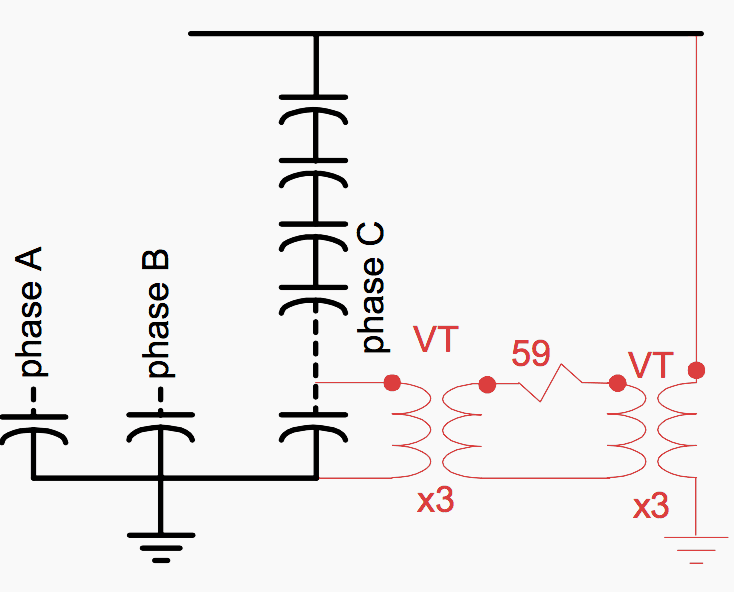
An equivalent zero sequence component that eliminate the system unbalances can be derived utilizing three voltage-sensing devices with their high side voltage wye-connected from line to ground, and the secondaries connected in a broken delta. The voltage source VTs can be either at a tap in the capacitor bank or used the VTs of the bank bus.
Figs. 1 (b) shows a neutral unbalance relay protection scheme for an ungrounded wye capacitor bank, using three phase-to-neutral voltage transformers with their secondaries connected in broken delta to an overvoltage relay.
Also, the unbalance voltage going to the overvoltage relay is three times the neutral voltage as obtained from Fig 1(a). For the same voltage transformer ratio, there is a gain of three in sensitivity over the single neutral-to-ground voltage transformer scheme. The voltage transformers should be rated for line-to-line voltage.
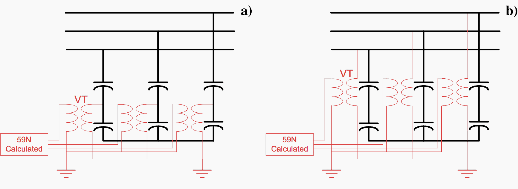
Modern digital relays can calculate the zero sequence voltage from the phase voltages as shown in Fig 2 (a), eliminating the need of additional auxiliary VTs to obtain the zero sequence voltage. Fig 2 (b) shows the same principle but using the VTs on the capacitor bank bus.
Although schemes shown in Fig 1(b), 2(a) and 2(b) eliminate system unbalances, they do not eliminate the inherent capacitor unbalance.
Figure 3 below shows a protection scheme that removes the system unbalance and compensate for the inherent capacitor unbalance. It is a variation of the voltage differential scheme for grounded banks.
The bank terminal zero sequence component is derived from 3 line VTs with their high side Wye connected and their secondaries connected in broken delta.
The difference voltage between the neutral unbalance signal due to system unbalance and the calculated zero sequence from the terminal VTs will be compensated for all conditions of system unbalance. The remaining error appearing at the neutral due to manufacturers capacitor tolerance is then compensated for by means of a phase shifter.
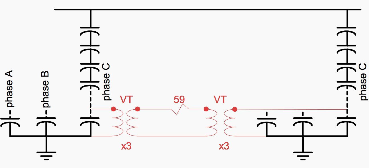
b) Unbalance Protection for Ungrounded Double Wye Banks
Ungrounded banks can be split into two equal banks. This bank configuration inherently compensates for system voltage unbalances.
However, the effects of manufacturers capacitor tolerance will affect relay operation unless steps are taken to compensate for this error.

Three methods of providing unbalance protection for double wye ungrounded banks are presented. Figure 4(a) uses a current transformer on the connection of the two neutrals and an overcurrent relay (or a shunt and a voltage relay). Figure 4(b) uses a voltage transformer connected between the two neutrals and an overvoltage relay.
The neutral current is one-half of that of a single grounded bank of the same size. However, the current transformer ratio and relay rating may be selected for the desired sensitivity because they are not subjected to switching surge currents or single-phase currents as they are in the grounded neutral scheme.
Although a low-ratio voltage transformer would be desirable, a voltage transformer rated for system voltage is required for the ungrounded neutral. Therefore, a high turns ratio should be accepted.
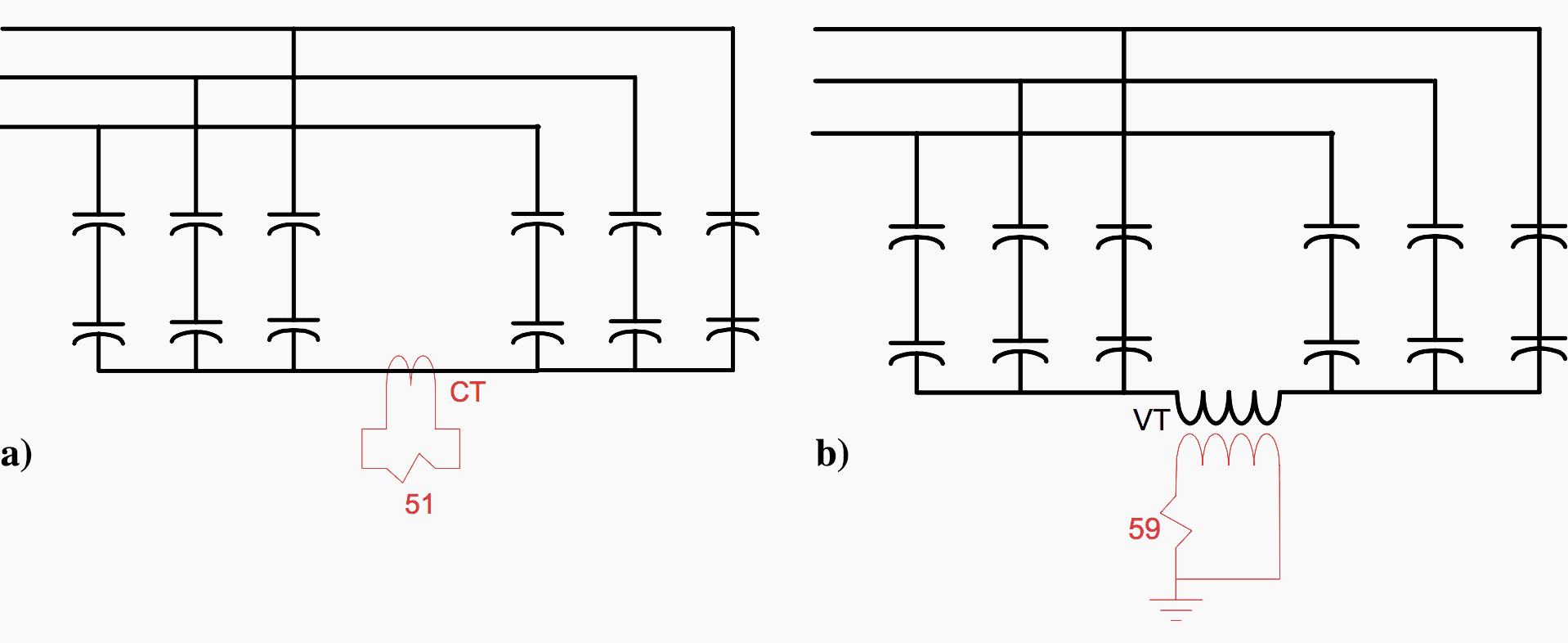
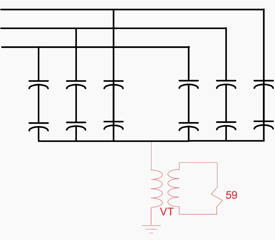
Figure 5 shows a scheme where the neutrals of the two capacitor sections are ungrounded but tied together. A voltage transformer, or potential device, is used to measure the voltage between the capacitor bank neutral and ground.
The relay should have a harmonic filter.
2. Unbalance Protection Methods for Grounded Wye Banks
a) Unbalance Protection for Grounded Single Wye Banks
An unbalance in the capacitor bank will cause current to flow in the neutral. Fig. 6 (a) shows a protection based on a current transformer installed on the connection between the capacitor bank neutral and ground. This current transformer has unusual high overvoltage and current requirements.
The ratio is selected to give both adequate overcurrent capability and appropriate signal for the protection.
The voltage across the burden resistor is in phase with the neutral-to-ground current. This neutral-to-ground current is the vector sum of the three-phase currents, which are 90° out of the phase with the system phase-to-ground voltages.
This scheme may be compensated for power system voltage unbalances, by accounting for the 90° phase shift, and is not unusually appropriate for very large capacitor banks requiring very sensitive settings.
Each time the capacitor bank is energized, momentary unbalanced capacitor charging currents will circulate in the phases and in the capacitor neutral. Where a parallel bank is already in service these current can be on the order of thousands Amps causing the relay to mal-operate and CT to fail.
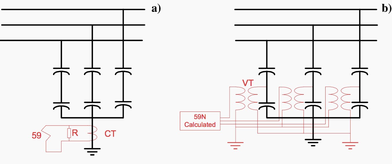
Figure 6 (b) presents an unbalance voltage protection scheme for single grounded wye connected SCB’s using capacitor tap point voltages. An unbalance in the capacitor bank will cause an unbalance in the voltages at the tap point of the three phases. The protection scheme consists of a voltage sensing device connected between the capacitor intermediate point and ground on each phase.
A time delay voltage relay with third harmonic filter is connected to the broken delta secondaries. Modern digital relays use the calculated zero sequence voltage instead as shown in Fig. 6(b).
b) Unbalance Protection for Grounded Double Wye Banks
Figure 7 shows a scheme where a current transformer is installed on each neutral of the two sections of a double Wye SCB. The neutrals are connected to a common ground. The current transformer secondaries are cross-connected to an overcurrent relay so that the relay is insensitive to any outside condition that affects both sections of the capacitor bank in the same direction or manner.
The current transformers can be subjected to switching transient currents and, therefore, surge protection is required. They should be sized for single-phase load currents if possible.
Alternatively, the connections from neutral to ground from the two wyes may be in opposite directions through a single-window current transformer.

c) Voltage differential protection method for grounded wye banks
On large SCBs with large number of capacitor units, it is very difficult to detect the loss of 1 or 2 capacitor units as the signal produced by the unbalance is buried in the inherent bank unbalance.
The voltage differential provides a very sensitive and efficient method to compensate for both system and inherent capacitor bank unbalances in grounded wye capacitor banks!
The scheme uses two voltage transformers per phase: one connected to a tap on the capacitor bank. The other, at the bank bus for single Wye banks; or, for double Wye banks, at a similar tap on the second bank. By comparing the voltages of both VTs, a signal responsive to the loss of individual capacitor elements or units is derived.
The capacitor bank tap voltage is obtained by connecting a voltage-sensing device across the ground end parallel group (or groups) of capacitors. This may be a midpoint tap, where the voltage is measured between the midpoint of the phase and ground.
Alternatively, the tap voltage may be measured across low-voltage capacitors (that is, a capacitive shunt) at the neutral end of the phase.
For commissioning, after checking that all capacitors are good and no fuses have operated, the voltage levels are initially adjusted to be equal. The initial difference signal between the capacitor bank tap voltage and the bus voltage (for single Wye banks) signals is zero, and the capacitor tolerance and initial system voltage unbalance is compensated.
Any subsequent voltage difference between capacitor tap voltage and bus voltage will be due to unbalances caused by loss of capacitor units within that particular phase. For double Wye banks, the tap voltage is compared the other Wye tap voltage.
Modern digital relay dynamically compensate secondary errors introduced by sensing device variation and temperature differences between capacitor units within the bank.
If the bank is tapped at the midpoint the sensitivity is the same for failures within and outside the tapped portion. If the bank is tapped below (above) the midpoint, the sensitivity for failures within the tapped portion will be greater (less) than for failures outside the tap portion.
Tapping across the bottom series groups or a midpoint tap is not appropriate for fuseless banks with multiple strings because the strings are not connected to each other at the tap point. Tapping across the low-voltage capacitors is suitable for fuseless capacitor banks.
33kV Capacitor Banks Improve Reliability
In this video function of the capacitor bank has been discussed with a different components.
Reference // Shunt Capacitor Bank Fundamentals and Protection by Gustavo Brunello, M.Eng, P.Eng, Dr. Bogdan Kasztenny and Craig Wester (all from GE Multilin, USA)
Related electrical guides & articles


Edvard Csanyi
Hi, I'm an electrical engineer, programmer and founder of EEP - Electrical Engineering Portal. I worked twelve years at Schneider Electric in the position of technical support for low- and medium-voltage projects and the design of busbar trunking systems.I'm highly specialized in the design of LV/MV switchgear and low-voltage, high-power busbar trunking (<6300A) in substations, commercial buildings and industry facilities. I'm also a professional in AutoCAD programming.
Profile: Edvard Csanyi

if active power is increased while reactive power remains the same?,