
Estimated Study Time: 13 minutes
Factory tests
This technical article briefly describes seven very important tests you should perform during commissioning of a dry-type transformer. Usually tests are performed in the factory where transformers are produced.
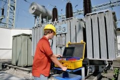
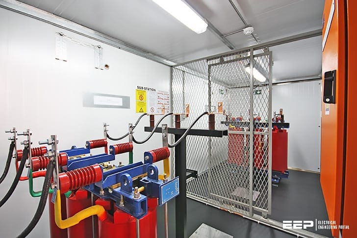 7 routine tests for a dry-type transformer you should perform during commissioning (photo credit: RWW Engineering)
Introduction to routine tests
The following routine tests must be carried out on all dry-type power transformers:
- Separate-source voltage withstand test
- Induced voltage test
- Voltage ratio measurement and check of polarities and connections
- No-load current and no-load loss measurement
- Winding resistance measurement
- Short-circuit impedance and load loss measurement
- Partial discharge measurement in accordance with IEC 60726 (for dry-type power transformers)
1. Dielectric tests – Separate-source voltage withstand test
The single-phase applied voltage wave shape shall be approximately sinusoidal. The test must be performed at rated frequency. At the end of the test, the test voltage shall be rapidly reduced up to 1/3 the full voltage before disconnection.
The test shall be performed on all the windings. The test is successful if no failure occurs at full test voltage.
2. Induced voltage test
The test voltage shall be twice the value corresponding to the rated voltage. It shall be applied between the terminals of the secondary windings, by maintaining the primary winding open. The duration of the test at full voltage shall be 60 s, and the frequency twice the rated value.
At the end of the test, the voltage shall be rapidly reduced up to 1/3 the rated value before disconnection. The test is successful if no failure occurs at full test voltage.
3. Voltage ratio measurement and check of polarity/connections
Voltage ratio measurement and check of polarities and connections shall be performed on all tap changer positions. The correspondence between the numbers assigned to the tappings and the ratings shall also be checked.
Voltage ratio measurement shall be performed phase by phase between the terminals of corresponding windings.
Voltage ratio measurement is carried out by use of potentiometric method.
4. No-load current and no-load loss measurement
This test is performed by supplying LV windings at rated frequency and rated voltage. The wave shape shall be as nearly as possible of the sine-wave and the primary windings shall be open.
The frequency of the test shall not differ from the rated value more than ± 1%. No-load current and loss shall be measured as well as the mean value and the effective value of the voltage.
No-load current shall result as the average value of three readings performed by effective value ammeters. Three wattmeters shall be used to measure the power, by using instrument transformers and transducers when necessary.

5. Winding resistance measurement
Winding resistance measurement shall be performed when the windings are at ambient temperature without supply for a time long enough to achieve this condition. The measurements shall be carried out in direct current between terminals according to the sequence U-V; V-W; WU.
Ambient temperature shall also be measured. It shall result as the average value of three measurements performed by apposite thermal sensors.
5.1 HV winding resistance measurement
HV winding resistance measurement shall be performed by measuring simultaneously voltage and current. The voltmeter and ammeter must be
connected as follows :
- Voltmeter terminals must be connected beyond current cables;
- The current shall not exceed 10% of winding rated current;
- The measurement shall be carried out after voltage and current are stable.
Unless otherwise agreed, the HV winding shall be connected on principal tapping.
5.2 LV winding resistance measurement
LV winding resistance measurement shall be performed by measuring simultaneously voltage and current.
The voltmeter and ammeter shall be connected as follows :
- Voltmeter terminals shall be connected beyond current cables;
- The current shall not exceed 5% of winding rated current;
- The measurement shall be carried out after voltage and current are stable.
6. Short-circuit impedance and load-loss measurement
The short-circuit loss and the short-circuit voltage show the performance of the transformer. These values are recorded and guaranteed to the customer and important for operational economy. The short-circuit voltage is an important criteria especially during parallel operations of the transformers.
The short-circuit loss is a data which is also used in the heat test.
The short-circuit loss is composed of “Joule“ losses (direct current/DC losses) which is formed by the load current in the winding and the additional losses (alternating current/AC losses) in the windings, core pressing arrangements, tank walls and magnetic screening (if any) by the leakage (scatter) fluxes.
Measuring circuit and performing the measurement:

Where:
1- Power supply
2- Supply (intermediate) Transformer
3- Current Transformers
4- Voltage Transformers
5- Power Analyser
6- Transformer under test
C- Compensation Capacitor groups
In general, the HV windings of the transformer are supplied while the LV windings are short-circuited.
During measurement, the current has to be at the value of IN or close to this value as far as possible. The voltage, current and short-circuit losses of each phase should be measured during measurement.
In order to avoid increasing the winding temperature by the applied current, the measurement has to be completed in a short time and the measuring current has to be kept between 25%…100% of the rated current. In this way, the measurement errors due to winding temperature increase will be minimized.
The losses have to be corrected based on reference temperature (e.g. 75°C ) stated in the standards and evaluated.
The short-circuit voltage and losses which are found at the temperature which the measurement was made, have to be corrected according to this reference temperature.
7. Partial discharge measurement
All PD measuring methods are based on the detection of PD current impulses i(t) circulating in the parallel‐connected capacitors Ck (coupling capacitor) and Ct (test object capacitance) via measuring impedance Zm.
The basic equivalent circuit for PD measurements is presented in figure 5.
Where:
- PDS = PD system
- Ck = coupling capacitor
- Ct = test object capacitance
- Z = voltage source connection
- Zm = measuring impedance
The measuring impedance Zm can either be connected in series with coupling capacitor Ck or with the test object capacitance Ct. PD current impulses are generated by charge transfers between parallel‐connected capacitor Ck (coupling capacitor) and Ct (test object capacitance).
Present IEC and IEEE Standards have both established rules for measuring and evaluating electric signals caused by partial discharges together with specifications on permissible magnitude. The IEC approach to the processing of the recorded electric signal is different from the IEEE approach.
The detection of apparent charge in pC is the preferred method now in use in IEEE Std. C57.113.
For the detection of apparent charge the integration of the PD‐current impulses i(t) is required.
Integration of the PD current impulses can be performed either in the time domain (digital oscilloscope) or in the frequency domain (band‐pass filter). Most PD systems available on the market perform a “quasi integration” of the PD current impulses in the frequency domain using a “wide‐band” or “narrow‐band” filter.
Circulating PD current impulses – generated by an external PD source (in the test circuit) or by an internal PD source (in the insulating system of the transformer) – can only be measured at the transformer bushings.
Bushing capacitance C1, represents the coupling capacitor Ck, which is connected in parallel with capacitance Ct (test object = total capacitance of the transformer insulating system).
UHF Partial Discharge Location Demonstration
Demonstration of UHF partial discharge location in a power transformer using time-of-flight techniques.
References:
- Guide to transformer testing by Tesar
- A Guide to Transformer Winding Resistance Measurements by Bruce Hembroff, (Manitoba Hydro), Matz Ohlen (Megger Sweden) and Peter Werelius (Megger Sweden)
- Transformer Tests by BEST Transformers
Related electrical guides & articles


Edvard Csanyi
Hi, I'm an electrical engineer, programmer and founder of EEP - Electrical Engineering Portal. I worked twelve years at Schneider Electric in the position of technical support for low- and medium-voltage projects and the design of busbar trunking systems.I'm highly specialized in the design of LV/MV switchgear and low-voltage, high-power busbar trunking (<6300A) in substations, commercial buildings and industry facilities. I'm also a professional in AutoCAD programming.
Profile: Edvard Csanyi

Not convinced why all routine tests, those are conducted in a Test Station have been mentioned as commissioning test. Few of those mentioned will not be feasible to conduct at site, where the Trafo will be commissioned.
short circuit value for dry type transformer 2000/2500/3150 kva
Hi.
Please can you credit the first picture on this page. This was a project designed and completed by RWW Engineering. It is not a Dry Type transformer but actually a harmonic filter reactor in a 5MVAR PFC bank.
Regards
Kyle Lass
Sure, Kyle, photo credit has been added. Thank you for noticing.
Thank you very much
Hi,
Wanted to know if tan delta test on dry type transformer is necessary as part of routine test or maintenance test.
Hi Edvard, at our site one of our dry type transformer burnt, we are troubleshooting for the root cause. Please contact us asap for further details.
Good job
Sir,
Which type winding is better Super enameled electrolyte copper or Foil copper for 3 PhTransformers (DTRs & PTRs).
Edvard Csanyi, how are you there, i like your posts of electrical engineering !!
is it possible to to have training in your company ?
Thanks for your lessons.Your portal is of high quality.
52Buxton St Doornfontein Johannesburg South Africa
New version of this literature is very useful https://library.e.abb.com/public/c1256b3c00492da6852570f8006d6175/1LAB000074_Testbook_intro.pdf