
Estimated Study Time: 14 minutes
Introduction to differential protection
Transformers are important system components available in many different constructions. The range of HV transformers reaches from small distribution transformers (from 100 kVA) up to large transformers having several hundred MVA.
 The essential physics behind transformer differential protection you should know (photo credit: Kam Abbott via Flickr)
Apart from a large number of simple two and three-winding transformers, a range of complex constructions in the form of multi-winding and regulating transformers also exist.
Differential protection provides fast and selective short-circuit protection on its own, or as a supplement to Buchholz (gas pressure) protection.
It is usually applied on transformers above approx. 1 MVA. On larger units above approx. 5 MVA is standard.
Essential physics
To better understand the protection response during short-circuits and switching operations, the physical principles of the transformer are initially covered in detail.
- Equivalent circuit of a transformer
- In-rush
- Sympathetic in-rush
- In-rush blocking
- Cross-blocking
- Transformer over-fluxing
1. Equivalent circuit of a transformer
The primary and secondary winding are linked via a magnetic core by means of the main flux Φ Figure 1. To obtain the flux, the magnetising current (excitation current) Im according to the magnetising curve is required.
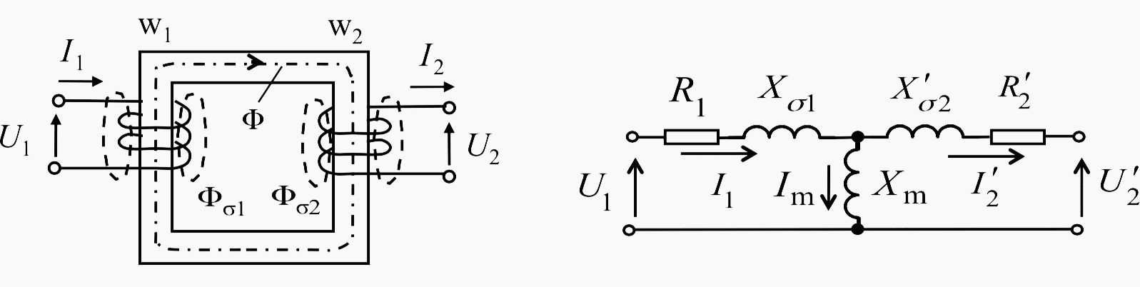
In the electrical equivalent circuit, this excitation requirement corresponds to the main reactance Xm. The leakage flux Φσ1 and Φσ2 are only linked to their respective own windings and make up the leakage reactances Xσ1 and Xσ2 .
R1 and R’2 are the respective winding resistances. All currents and impedances are referred to the primary side.
Xm = U/Im corresponds to the slope of the magnetising curve. During load and particularly in the event of short-circuits, the operating point is below the knee-point in the steep portion of the curve.
During load and short-circuit conditions, a simplified equivalent circuit may therefore be used for the calculations (Figure 2).

The series reactance XT corresponds to the short-circuit voltage in %, relative to the nominal impedance of the transformer:
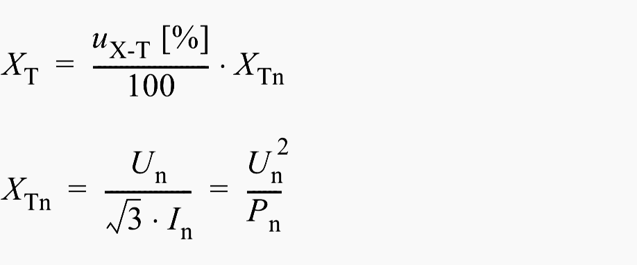
The series resistance corresponds to the ohmic short-circuit voltage in %, and is also based on the nominal impedance. For calculation of the short-circuit current, the resistance may be neglected, it must only be considered when calculating the DC time constant.
Table 1 lists typical transformer data.
Table 1 – Typical transformer data
| Rating [MVA] | Transformation ratio [kV/kV] | Short-circuit voltage ux-t [%] | Open circuit current [% IN] |
| 600 | 400/230 | 19 | 0.25 |
| 300 | 230/110 | 24 | 0.1 |
| 40 | 110/10 | 17 | 0.1 |
| 16 | 30/10 | 8.0 | 0.2 |
| 6.3 | 30/10 | 7.5 | 0.2 |
| 0.63 | 10/0.4 | 4.0 | 0.15 |
2. In-rush
When energizing a transformer, one-sided over-excitation results, due to remanance causing large magnetising current flow (in-rush current).
The flux does not return to zero when the transformer is switched off, but remains at the remanance point ΦRem, which may be above 80% of the nominal induction. When the transformer is re-energized, the flux increase starts at this point. Depending on the energizing instant on the sinusoidal voltage (point on wave), an off-set course of the flux can result.
The curve form corresponds with the sinusoidal half-waves of a simple half-wave rectified AC current that decays with a very large time constant (Figure 3 below).
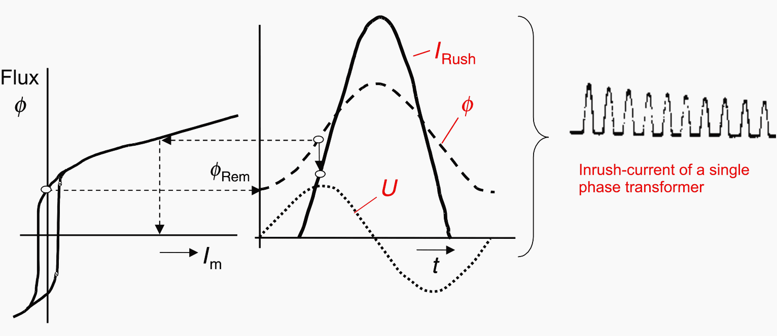
The rush current is particularly large when cores of cold rolled steel with a nominal induction (1.6 to 1.8 Tesla) are operated close to the saturation induction (approx. 2 Tesla).
On a three-phase transformer, a three-phase rush current will result, which depends on the vector group and the method of star-point earthing on the transformer.
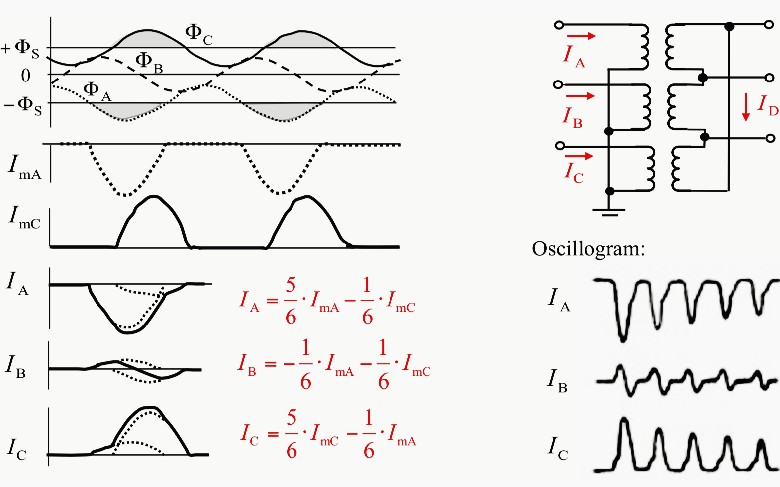
In general, two phases will saturate and draw large magnetising currents. On star delta transformers, these currents are coupled to the non-saturated phase via the delta winding.
This causes the typical rush currents as shown in Figure 5.
The rush currents in the three phases can be calculated from the required magnetisation (ImA and ImC) of the two saturated core-limbs A and C with the given equations. The current on phase B thereby corresponds to the current in the delta winding ID. The shown oscillogram of an in-rush occurrence confirms the calculated curves.
Amplitude and time constant depend on the transformer size (see figure 4).

It must be noted that a similar rush current also arises when a close-in external short–circuit is switched off and the transformer is re-magnetised by the recovery of the voltage.
It however is substantially smaller than the in-rush following ener- gising of a switched-off transformer.
Large rush currents can also occur when asynchronous systems are switched together via a transformer, as the large voltage difference can cause transient saturation of the core.
3. Sympathetic in-rush
When transformers were connected in parallel, it was observed that the differential protection of the transformer that was in service issued a trip.
The reason for this is sympathetic in-rush current, which results from the rush current of the transformer that is being energized (Figure 6).
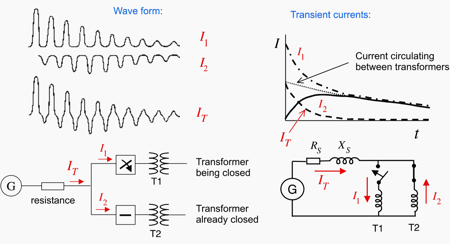
The voltage drop resulting from the initial rush current across the source resistance of the in-feed affects the second transformer in parallel and causes the sympathetic in-rush current (I2).
The current from the system (IT) decays rapidly. However a current still circulates between the two transformers due to the small damping (large time constant τ = X/R of the windings).
4. In-rush blocking
The in-rush current flows into the protected object from a single side and appears as an internal fault. The transformer differential protection must therefore be stabilized against this phenomenon.
The large amount of second harmonic in the rush current was already used with conventional protection for this purpose. The second harmonic is filtered out of the differential current (operating current) by means of a filter, and is then used as additional restraint current in the measuring bridge.
Other manufacturers compared the 100(120) and 50(60) Hz components directly with a separate bridge circuit, which then directly blocked the protection, as it is now done in the software of numerical protection.
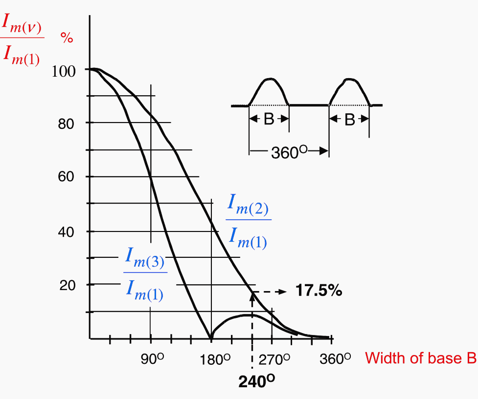
The 100(120) Hz component in the rush current depends on the base width of the sinusoidal caps (as shown in Figure 7).
It decreases as the base width B increases.
Investigations have shown that a base width greater than 240° hardly ever arises in practice, which implies a minimum second harmonic component of 17.5%. A setting of 15% therefore makes sense for in-rush blocking.
The 3rd harmonic may not be used for in-rush blocking, as it is strongly represented in the short-circuit current when CT saturation takes place.
A more sensitive setting than 15% of the second harmonic should normally not be applied as the off-set short-circuit current will also have a second harmonic component in case of CT saturation.
5. Cross-blocking
This function, which was already applied in conventional relays, is now available in all numerical relays and may be activated, if desired.
It takes into account that the second harmonic component in the individual phases is different and may not be sufficient, in the phase with the smallest component, to activate the blocking.
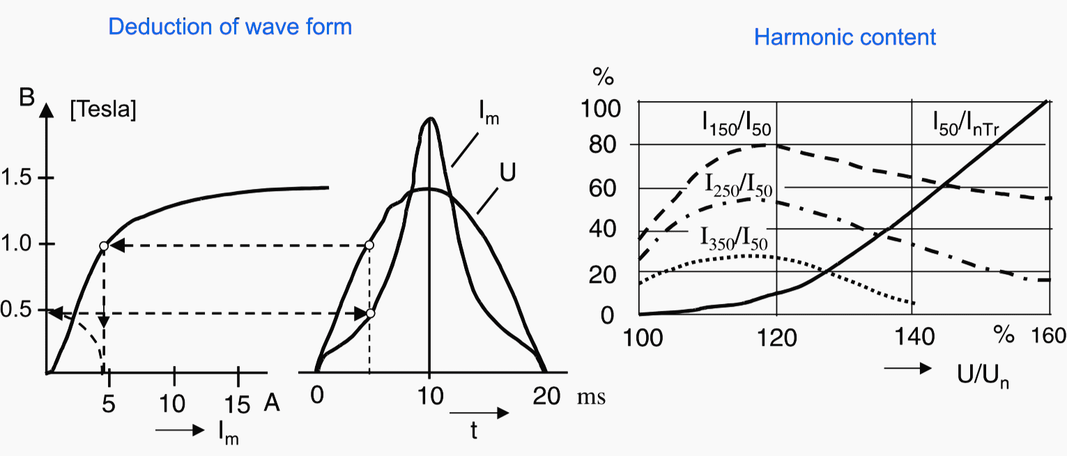
6. Transformer over-fluxing
If the transformer is operated with excessively high voltage, then the required magnetization is also increased. The magnetizing current rises sharply when the operating point on the magnetizing curve is close to the point of saturation.
The wave form becomes more and more distorted with increasing odd harmonic content (as shown in Figure 8).
The increased magnetising current appears as a tripping current in the differential protection with large overvoltage. This can cause tripping, depending on the con- figuration of the transformer.
Overvoltages can occur in the system, due to the distribution of reactive power flow in the event of tap changer problems, or following load shedding. This is particularly true for geographically large systems with long lines.
The transformer can tolerate the over-excitation, which causes heating, for a given time without sustaining damage. During this time the system regulation must ensure that the voltage returns to the permissible range.
Only if this does not occur, must the transformer be isolated by a special over-excitation protection having a U/f-dependent time delay. Tripping by the differential protection with a fast measurement due to these conditions must be avoided at all cost.
For this setting it must be noted that the 5th harmonic component again decreases if the over-voltage is very large (Figure 8). A typical setting is 30%.
If the over-voltage is very large, blocking is no longer sensible as the transformer is at risk. The blocking can therefore again be re-set when the 5th harmonic component is above a set ratio of the 50 Hz component, which increases as the over-voltage increases.
Reference // Numerical Differential Protection by Gerhard Ziegler
Related electrical guides & articles


Edvard Csanyi
Hi, I'm an electrical engineer, programmer and founder of EEP - Electrical Engineering Portal. I worked twelve years at Schneider Electric in the position of technical support for low- and medium-voltage projects and the design of busbar trunking systems.I'm highly specialized in the design of LV/MV switchgear and low-voltage, high-power busbar trunking (<6300A) in substations, commercial buildings and industry facilities. I'm also a professional in AutoCAD programming.
Profile: Edvard Csanyi

Muchas gracias por la informacion
¿ es posible información por calculo de correccion de factor de potencia , teniendo en cuenta la distorsion armonica
Very informative. Thanks
Very informative. Thanks.
Hi Edvard
Great job . Thanks
I am an electrical engineering student
i can’t save to pdf
Can this protection scheme be applied to Variable Frequency Transformers used on asynchronous networks
excellent information
Very good article. Thank you.
You said there like:
…”It is usually applied on transformers above approx. 1 MVA. On larger units above approx. 5 MVA it is standard.”…
For this could you provide standard reference , if any, by revert email.
Thank you in advance and regards
very nice information regarding transformer.
i need to know some pointers of transformer
Thank you very much for above information.
Can you please explain in detail about behavior of distribution lines (medium voltage) when any fault occurs on downstream side or during any transformer charging on downstream side having overhead or underground cables attached with the transformer.