Understanding polarity
Polarity is very important for the operation of transformers and protection equipment. A clear understanding of polarity is useful in understanding and analyzing transformer connections and operations as well as testing protection relays and systems.

It’s also essential in understanding power system performance during both normal and abnormal operations.
1. Transformer polarity
The polarity indications for transformers are well established by standards that apply to all types of transformers. There are two varieties of polarity: subtractive and additive. Both follow the same rules.
Power and instrument transformers are subtractive, whereas some distribution transformers are additive. The polarity marking can be a dot, a square, or an X, or it can be indicated by the standardized transformer terminal markings, the practices varying over the years.
Polarity is designated by an X in this technical article.


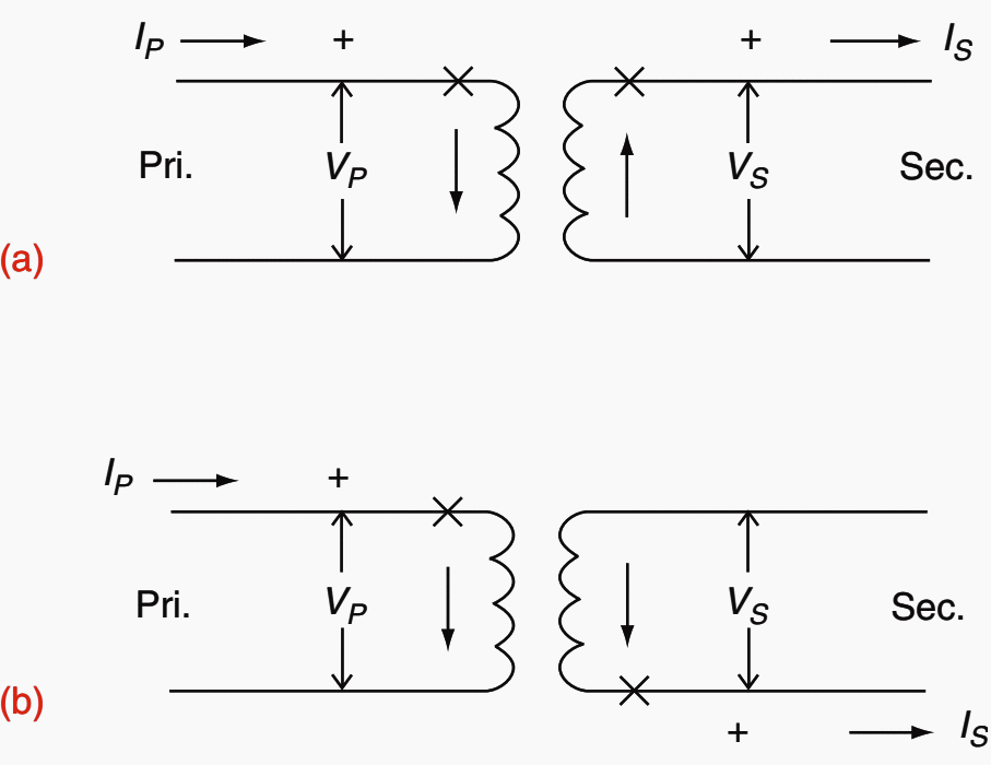
The two fundamental rules of transformer polarity, illustrated in 1 applying to both varieties are the following:
- Current flowing in at the polarity mark of one winding flows out of the polarity mark of the other winding. Both currents are substantially in-phase.
- The voltage drop from polarity to non-polarity across one winding is essentially in phase with the voltage drop from polarity to non-polarity across the other winding(s).
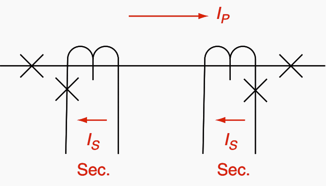
The current transformer (CT) polarity markings are shown in Figure 2.
Note that the direction of the secondary current is the same, independent of whether the polarity marks are together on one side or on the other.


For CTs associated with circuit breakers and transformer banks, it is a common practice for the polarity marks to be located on the side away from the associated equipment.
The voltage-drop rule is often omitted in the definition of transformer polarity, but it is an extremely useful tool to check the phase relations through wye–delta transformer banks, or in connecting up a transformer bank for a specific phase shift required by the power system.
The connections for these two cases are shown in Figures 3 and 4. The diagrams below the three-phase transformer connection illustrate the use of the voltage-drop rule to provide or check the connections.
Arrows on these voltage drops have been omitted (preferably not used), for they are not necessary and can cause confusion.


In Figure 3, the check is made by noting that a to n from polarity to non-polarity on the left-side winding is in phase with A to B from polarity to non-polarity on the right-side winding.
Accordingly, the wye side would be the high-voltage side if this is an ANSI/IEEE standard transformer.


This same technique of applying voltage drops to Figure 4 shows that for this three-phase bank connection the voltage-drop polarity to non-polarity or phase a to n is in phase with the voltage-drop polarity to non-polarity or phase A to phase C.
Similarly, voltage-drop across phase b to n is in phase with voltage-drop phase B to phase A, and voltage-drop phase c to n is in phase with voltage-drop across phase C to phase B.
By comparing similar voltages on the two sides of the transformer, phase-A-to-neutral voltage drop leads the phase-a-to-n voltage drop by 30°, so the delta winding would be the high-voltage side if this is an ANSI/IEEE standard transformer bank.
Because the ANSI/IEEE standards have been in existence for several years, most transformer banks in service today follow this standard, except where it is not possible because of pre-existing system conditions.
Transformer Polarity Explained by an Electrician (VIDEO)
2. Relay polarity
Relays involving interaction between two input quantities from the power system may have the polarity marking that is necessary for their correct operation.
There are no standards in this area, so if the polarity of the relay connections is important, the relay manufacturer must both specify the polarity markings and clearly document their meaning.
Directional units are usually not applied alone, but rather, in combinations with other units, such as fault sensors or detectors. A common practice is to use the output of the directional-sensing unit to control the operation of the fault sensors, which often is an instantaneous or an inverse-time–overcurrent unit, or both units together.
Three conditions must be satisfied for its operation: current magnitude, time delay and directionality. The directionality of current flow can be identified using voltage as a reference of direction.
Thus, if the current flow is in the desired operating direction (trip direction) and its magnitude is greater than the fault sensor’s minimum-operating current (pickup), the relay can operate. If the current is in the opposite direction (non-trip or non-operate direction or zone), no operation can occur even though the magnitude of the current is higher than the pickup threshold current.
A directional-sensing unit requires a reference quantity that is reasonably constant, against which the current in the protected circuit can be compared.
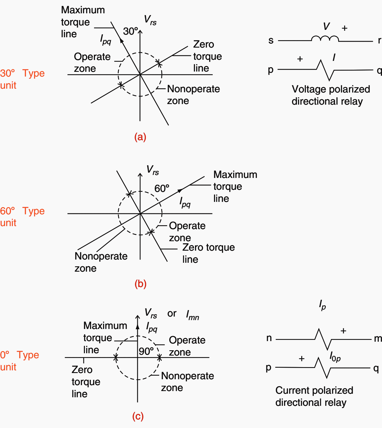
Typical polarity indications for three commonly used directional-sensing units are shown in Figure 5.
This uses the custom of showing several loops for voltage coils and a single loop for current coils, of placing the reference circuit or voltage circuit above the current circuit, and of placing the polarity markings diagonally, all as shown on the relay schematics in Figure 5.


The reference quantity is commonly called the ‘‘polarizing’’ quantity, especially for ground-fault relaying, where either current polarizing or voltage polarizing is used, or both.
The polarity marks (Figure 5) are small plus symbols (+) placed, as illustrated, above one end of each coil, diagonally as shown, or on the opposite diagonal.
As shown in Figure 2 above, relay operation is not affected whether the polarity marks are on one diagonal or the other. The meaning of the polarity for a specific relay must be stated clearly in words or by a diagram, such as the one shown in Figure 5. These show the basic design characteristics of an individual relay, independent of any connection or association with the power system.
The interpretation of relay polarity is illustrated in Figure 5 for three typical electromechanical units.
Solid-state units can have adjustments for (1) the maximum-torque angle and (2) the angle limits of the operate zone, but the application and operation is the same for both types.
In Figure 5a, the maximum-operating torque or energy occurs when the current flows from polarity to non-polarity (Ipq) and leads by 30° the voltage drop from polarity to non-polarity (Vrs). The minimum pickup of the directional unit is specified as the maximum-torque or operating condition
As seen, the unit will operate for currents from almost 60° lagging the reference voltage Vrs to almost 120° leading. The operate (trip, contact close) zone or area is represented by the half plane, bordered on one side by the zero-torque (non-operating) line and extending in the direction that contains both the reference (polarizing) and operating quantities.
Higher-current values will be required when Ipq deviates from the maximum-torque line. The solid-state relays can adjust this torque line for increased sensitivity by adjusting it to the fault line.
The operating torque at any angle is a function of the cosine of the angle between the current (Ipq) and the maximum-torque line, as well as the magnitudes of the operating quantities. For ground-fault protection, the 60° unit in Figure 5b is used with a 3 V0 reference and the zero (watt) unit of Figure 5c with a 3 I0 current reference. The unit in Figure 5c is also used for power or var applications.
A similar type of electromechanical directional unit, as in Figure 5a, has its maximum-torque angle at 45° leading, instead of 30° leading. Both units are in wide use for phase-fault protection.
Solid-state units with an adjustable angle feature can provide a range of angles.
Directional Earth fault Protection 67N Example
This video shows us how to test a directional earth fault protection 67N using the appropriate TDMS application. The tested relay is ISA Demo Relay with standard settings.
Reference // Protective Relaying Principles and Applications by J. Lewis Blackburn and Thomas J. Domin (Purchase from Amazon


Thanks for the article.
Why, for the 60° unit (figure 5.b) the MTL is *lagging* 30° from Vrs, while, for the 30° unit, the MTL is *leading* from Vrs?
Hi. l enjoy reading your articles. Do you have articles of how to read protection control diagrams and Ac wiring diagrams.I am still a student .Please help
Such a great knowledge being shared. Thanks for your efforts.
I’ve been told (by who, I don’t remember) that there is a logical “reason” for reversing the polarity from additive to subtractive on larger/high voltage transformers. First of all, an additive polarity transformer is easier to manufacture because the H and X windings are wound in the same direction. So, why change the direction of the windings if its a more difficult manufacturing process?
Answer: A subtractive polarity configuration will have a smaller footprint, which is actually less expensive in the long run. The reason that they can be made smaller is due to the interaction of the H and X magnetic flux during fault conditions. So if a large transformer has a subtractive polarity then the spacing between H and X bushings can be decreased. This makes the transformer physically smaller than it would be if it had an additive configuration.
Remember: I’m just the messenger. Hopefully somebody smarter than me can add to this or completely debunk this sort of reasoning…!!
Good knowledge regarding transformer.
Nice topic..it is really informative and helpful to electrical practitioners.
More Power
Hi Dear Edvard ! Thanks for sharing this article and videos with us. I really liked this.
Hi,
I read your articles and enjoy it.
Would you publish articles on syncronisation of two incomer and buscoupler in MV Switchboard.
And its suitable allowed Voltage difference And time delayed settings.
Thanks..
do you have any article on surge protection