
Estimated Study Time: 16 minutes
Selecting and rating MV switchgear
It’s not unusual to see that engineers mix terms of primary ratings. If they are not understood well, yes, it’s possible to mix some of them. But it’s essential to differentiate them. This technical article will try to shed some light on the fundamental primary rated values involved in correct selecting and rating the medium voltage switchgear assembly and its main components.
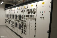
 Primary rated values for medium voltage switchgear (on photo: Medium voltage switchgear, type NXAIR by SIemens; credit: Maximilian Huelsing via Linkedin)
Just to mention that the process of designing secondary systems with devices for protection, control, measurement, and counting purposes is not covered here.
- Rated voltage (Ur)
- Rated insulation level
- Rated short-circuit currents
- Rated duration of short-circuit (tk)
- Rated normal current (Ir)
1. Rated voltage Ur
Definition – The maximum operating voltage of the network (UNmax) – at the upper tolerance limit – and the required insulation level of the equipment determine the rated voltage.
Rating rule: Ur ≥ UNmax and Ur corresponds with the required insulations level (see 2. below)
If a particular insolation level is pre-determined, the rated voltage must correspond with it.
Recommendations:
Recommendation №1 – The rated voltage of the switchgear may differ from that of voltage transformers, surge arresters, and HRC fuses. This is because these devices are subject to additional rating criteria .
Recommendation №2 – Some switching duties require the switching devices to have an even higher rated voltage, although this is rare. In certain cases, the entire switchgear system must be designed for higher voltages.
Recommendation №3 – Due to the reduced insulating properties tt altitudes of above 1000 m above sea level, a higher rated value may be selected – where applicable (see 2. below).
Recommendation №4 – A higher rated voltage can be set to fulfil the requirements of a higher insulation level in order to cope with special ambient conditions, for example pollution or humidity. (see 2. below).
2. Rated insulation level
The insulation level comprises the lightning impulse withstand voltage (Up) and the short-duration power-frequency withstand voltage (Ud).
Rating rule: Ur ↔ Ud and Up (see table in IEC 62271-1)
The rated insulation level is assigned to the rated voltage in accordance with table 1a, IEC 62271-1 [1] the applicable standard and is, therefore, set at the same time as the rated voltage. Different allocations must be specified separately.
In medium-voltage systems, the standard insulation levels do not differ with respect to the neutral point earthing
Table 1 – Rated voltages and insulation levels in the medium voltage range
| Rated voltage Ur/kV (r.m.s. value) | Rated short-duration power-frequency withstand voltage Ud / kV (r.m.s. value) | Rated lightning impulse withstand voltage Up / kV (peak value) | ||
| Line-earth, line-line, across contact gap | Across isolating distance | Line-earth, line-line, across contact gap | Across isolating distance | |
| (1) | (2) | (3) | (4) | (5) |
| 3.6 | 10 | 12 | 20, 40 | 23, 46 |
| 7.2 | 20 | 23 | 40, 60 | 46, 70 |
| 12 | 28 | 32 | 60, 75 | 70, 85 |
| 17.5 | 38 | 45 | 75, 95 | 85, 110 |
| 24 | 50 | 60 | 95, 125 | 110, 145 |
| 36 | 70 | 80 | 145, 170 | 160, 195 |
| 52 | 95 | 110 | 250 | 290 |
Comments:
Recommendation №1 – Operators may specify a higher insulation level in accordance with operational requirements. Reasons for this include foreseeable reduction in insulation due to moisture or pollution or high dielectric stresses during standard operation due to connected overhead systems, traction supply systems etc.
Recommendation №2 – At altitudes of at least 1000 m above sea level, the insulation level decreases caused by the
lower air density.
There are alternatives to compensate this decrease:
- A higher rated voltage is set.
- Surge arresters are installed to limit possible overvoltages below the actual insulation capability. Based on the voltage withstand value at the relevant altitude (see Figure 1) the required protection level of the arresters is determined.
- Gas-/solid-insulated switchgear is used with shielded, earthed connections (cable plug connectors, insulated bars), where the HV conductors are nor surrounded by ambient air.
For low-voltage auxiliary and control equipment no precautionary measures need be taken up to 2000 m altitude. Regarding installation sites at higher altitude see IEC 60664-1 [18].

Example for diagram above: a lightning impulse withstand voltage of Up = 120 kV is required at an altitude of 1800 m. A system with a rated voltage of 36 kV achieves this, while a 24 kV system is not suitable because it can only maintain a lightning impulse withstand voltage of 125 kV up to 1000 m.
Recommendation №3 – In environments with high levels of pollution, longer creepage paths may be required. This can be achieved not only with a higher insulation level, but also with alternative methods:
- Avoiding unprotected insulation
- Additional insulation for exposed parts (e.g. heat shrink tube to act as bridging protection)
- Gas-insulated switchgear with shielded, earthed connections (cable plug connectors, insulated bars)
Note that, in many cases, surge arresters fitted at central points can be used as an alternative to increasing insulation levels.
3. Rated short-circuit currents
Rated short-circuit currents include:
- The peak current Ip and short-circuit making current Ima
- The short-time current Ik and short-circuit breaking current Isc
The peak current and short-time current are withstand capability variables (steady state), while the short-circuit making and breaking current indicate the switching capacity. The applicable standard defines a fixed ratio between the impulse and short-time current as a basic design requirement for switching devices and switchgear: Ip/Ik = 2.5 (2.6 at 60 Hz).
The same ratio applies to the dynamic variables Ima/Isc. The values that actually occur in the network, however, have priority.
Related electrical guides & articles


Edvard Csanyi
Hi, I'm an electrical engineer, programmer and founder of EEP - Electrical Engineering Portal. I worked twelve years at Schneider Electric in the position of technical support for low- and medium-voltage projects and the design of busbar trunking systems.I'm highly specialized in the design of LV/MV switchgear and low-voltage, high-power busbar trunking (<6300A) in substations, commercial buildings and industry facilities. I'm also a professional in AutoCAD programming.
Profile: Edvard Csanyi
