
It’s all about losses and vars…
For a power system to operate efficiently and securely, the importance of the correct and coordinated provision and control of reactive power cannot be overemphasised. It is necessary to examine reactive power requirements under both steady-state and dynamic conditions. Although it has been normal in the past to consider these requirements separately, it is preferable that they should be dealt with in a well-coordinated way.
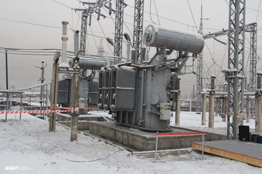 Parameters of generators, transformers, lines and cables important for vars and voltage control
In electrical power systems, electrical energy is produced by generators, transferred by means of transformers into a transmission system by which it is conveyed to distribution systems and supplied, again via transformers, to the users of the energy.
The International Electrotechnical Commission, IEC, has defined the unit for reactive power as the ‘var’ (volt-ampere reactive) and uses the name ‘vars’ for reactive power. For brevity, the IEC terminology will generally be used within this article.
Characteristics of system components:
Characteristics of system components
1. Generators
The generator is the heart of the power system. The main generator parameters relevant to the var balance in a system are the transient reactance and the short-circuit ratio (SCR) which is approximately the reciprocal of the synchronous reactance). Where transient stability is to be examined, or where var control is required to be used for the damping of system oscillations, the inertia of the turbine-generator combination also needs to be known.
To obtain economies from standardization, many manufacturers of turbo-generators will offer a machine from a standard range of frame sizes; different combinations of megawatts, rated power factor and short-circuit ratio are possible with each design of the range.
However, unity PF operation may not be acceptable for the stability and optimum operation of the network. Operation of a generator at a lagging power factor, i.e. when generating vars, requires a higher level of field excitation than at unity PF. This reduces the generator load angle for given power output.
To prevent a generator from losing synchronism during angular swings following a system disturbance, it is desirable to operate it in a steady state with an adequate margin of load angle from its stability limit.
A typical cylindrical-rotor turbogenerator will have a short-circuit ratio in the range 0.45−0.6. This would require operation at around 0.9−0.95 lagging PF, as shown in the capability chart in Figure 2 if the generator is feeding into a reasonably strong system.
Under these conditions the generator will be supplying a significant amount of vars to the system, amounting to 0.48−0.33 Mvar/MW of output.
When it is necessary for a generator to absorb vars (i.e. to operate at a leading PF ), as occurs during light load conditions for generating stations supplying remote load centres through long high-voltage lines, the field excitation must be lower than that at unity PF. The generator must then be designed to maintain stability, which requires that positive excitation be needed under all conditions.
This gives a design with a short-circuit ratio (SCR) of, say, 1.0−1.5. Such high values are common in salient-pole low-speed generators in hydroelectric stations, which account for most such applications. Such a high value is unusual in round-rotor turbogenerators and would require an unusually large machine for the MW output.
It may be more appropriate to provide var absorption equipment within the transmission network in these circumstances. The proportion of the system var requirements supplied by generators varies from system to system.
The operating PF may, in practice, be dictated more by stability than load requirements and it is quite usual for generators to be operated at a lagging PF higher than their rated value.
Suggested to Study – My experience in the first synchronization of the MV generator in an industrial plant
My experience in the first synchronization of the MV generator in an industrial plant
Go back to the Contents Table ↑
2. Transformers
Although generators are now becoming available which are suitable for connection directly to system voltages of 145 kV and higher, in most cases it is necessary to couple the generator to the transmission system by means of a transformer. Similarly, transformers are used to reduce the voltage level at the points of connection of the distribution companies and again for the supply of individual customers or groups of customers.
They are also used between the different voltage levels used by the transmission company or companies.
The transformer leakage reactances have great significance for the operation of the transmission system. Although the power loss and magnetising current of a transformer can be neglected when considering var flows, the var absorption in its leakage reactance (given by I2X) is important.
On-load tap-changing of transformers is a useful function in the coordination of var control between various voltage levels within a system and for balancing var flows within a single voltage level.
Two distinct practices occur with transformers used to interconnect different transmission voltage levels in a single system; a number of authorities, with a view to using transformers having the highest reliability, install fixed-ratio transformers, whereas others use on-load tap-changers having a typical total range of 20−30%.
For the interconnection of transmission networks to sub-transmission or distribution networks, the use of tap-changing transformers is almost universal.
Suggested Courses – Complete Power Engineering Bundle (Six Courses)
Learn fundamentals of power system analysis, generators, transformers and transmission lines, to calculate load flow & short circuits, and to perform power system stability analysis. This bundle includes six courses in a total duration of 22 hours 19 mins.
Go back to the Contents Table ↑
3. Transmission lines and cables
Transmission lines and cables absorb vars in their series inductance. They also have an inherent capability to generate vars by their shunt capacitance, which causes a reactive ‘charging current’ to flow into the line. Both the series inductance and the shunt capacitance are distributed along the length of the line.
From the analytical point of view, cables are indistinguishable from overhead lines except that the ratio between shunt capacitance and series reactance is considerably higher. The use of cables in high-voltage networks is increasing because of the difficulties of building new overhead lines for electrical power transmission into urban areas and, to a more limited extent, for a.c. underwater links.
When there is no load current flowing through a line or cable, it is found that the voltage at the receiving end of the line is higher than that at the sending end; this is caused by the flow of the capacitive charging current through the series inductance and is known as the Ferranti Effect.
Suggested studying – The mystery of nuisance tripping incidents in transformer protection that worry engineers
The mystery of nuisance tripping incidents in transformer protection that worry engineers
The magnitude of the voltage rise increases very rapidly with the increasing length of the line, from only about 3% for 200 km to about 50% for 800 km. The magnitude of such a voltage rise within a transmission system must be limited (generally to either 5 or 10% above rated voltage), in order to avoid exceeding the safe limits of operation for the insulation of the line or cable itself as well as the safe limits for the various equipment connected to the transmission system.
Very long lines are normally split into sections 200 to 300 km long; voltage or var control measures can then be applied at the intervening substations, if required.
As the power flowing through the line is increased, the var absorption in the series reactance also increases. There is a critical current at which the magnitude of ‘series vars‘ absorbed in the line is just enough to balance the ‘shunt vars‘ generated by the shunt capacitance of the line. With this level of power flow, the line voltage will have the same value all along the line (neglecting resistive losses).
When there is a further increase in power flowing through the line, the vars absorbed will outweigh the vars generated and the voltage at the receiving end of the line will start to fall very rapidly with increasing load and may reach the point of complete collapse.
Surge-Impedance Load (SIL)
The surge impedance of a transmission line having series inductance L and shunt capacitance C is a resistance equal to √(L/C). If a load that has this value of resistance is connected to the end of the line, the power that flows into the load is called the Surge-Impedance Load or SIL.
This is the load, mentioned above, at which the var absorption in the series reactance equals the var generation in the shunt capacitance, and for which the voltage along the line is constant.
For a given surge impedance, the SIL increases in proportion to the square of the line voltage. The value of surge impedance for a 132 kV line is about 400 Ω.
For higher voltage systems, multiple conductors are normally used, in part to reduce corona effects, and the series inductance is also somewhat lower, giving a surge impedance of about 250Ω to 300Ω for a 400 kV line. One effect of choosing an increased transmission voltage is to reduce transmission losses at a given power flow, but another effect is to enable an improved power transmission capability per right of way.
In selecting a transmission voltage, therefore, a balance must be struck between equipment costs, operating costs and future capacity. The SIL of typical cables usually exceeds their rating, so that cables generate more vars than they absorb and compensation is often required. This imposes a limit to the uninterrupted length of cable that can be used.
For example, for submarine cables, the limit is typically 50−75 km before the capacitive charging current reaches the current rating of the cable.
Interesting power system lecture – Surge Impedance Load and Nose Curve
Cables that use cross-linked polyethylene (XLPE) insulation are now available for transmission voltages of 400−500 kV; for a 400 kV, 1100 MVA XLPE cable design, the SIL is about 2500 MW, which is still much higher than the rating. Nevertheless, these cables generate rather less charging current than the earlier types and allow uninterrupted lengths of up to about 100 km.
Where longer distances are required, another solution becomes necessary, for example, High Voltage Direct Current (HVDC) systems or a gas-insulated transmission line (GIL).
Most countries have two or three transmission voltage levels within their systems, the highest normally being in the 400−500 kV range, with a few countries in North and South America and the USSR operating or installing networks in the 750 kV range.
Although the use of UHV at 1000−1500 kV is technically feasible, the expense is high and its commercial application seems likely to be limited for the foreseeable future.
Suggested Reading – Major steps in designing generation and power evacuation in large hydropower plants
Major steps in designing generation and power evacuation in large hydropower plants
Go back to the Contents Table ↑
4. Loads
In general, loads are inductive and their power factor can vary widely, dependent on the type, from industrial through commercial to domestic loads, and on location (for example, commercial and domestic loads in hot climates have an increasing proportion of motors for air conditioning).
In most studies, load representation as constant impedances (or constant P and Q) is adequate but, when studying dynamic conditions involving wide variations in voltage, a more detailed representation that allows for changing power factors will be required.
The following article “Practical design knowledge in harmonics distortion and power factor correction (PFC)” can be very useful in understanding the essentials of power factor correction.
Practical design knowledge in harmonics distortion and power factor correction (PFC)
Air-conditioning and many industrial loads use induction motors. When these comprise a substantial proportion of the total load on a network they display a typical voltage stability challenge. A short interruption due to a fault causes each motor to slow down. When the fault is removed and the voltage re-established the motor tries to regain full speed but, because of the increased slip, there is an increased var demand.
Loads that can produce network disturbances or distortions require special attention. These are, in the main, found in the metal and mining industries and in AC traction systems; the large and rapid fluctuations in the load currents of arc furnaces and large thyristor drives, particularly their fluctuating var demands, can cause annoyance to other customers.
These loads often also cause problems due to the generation of harmonics.
Suggested Course – ETAP Power System Design and Analysis Course For Solving Various Practical Problems
ETAP Power System Design and Analysis Course For Solving Various Practical Problems
Go back to the Contents Table ↑
Reference: Electrical Engineer’s Reference Book by M. A. Laughton CEng., D. J. Warne CEng.
Related electrical guides & articles


Edvard Csanyi
Hi, I'm an electrical engineer, programmer and founder of EEP - Electrical Engineering Portal. I worked twelve years at Schneider Electric in the position of technical support for low- and medium-voltage projects and the design of busbar trunking systems.I'm highly specialized in the design of LV/MV switchgear and low-voltage, high-power busbar trunking (<6300A) in substations, commercial buildings and industry facilities. I'm also a professional in AutoCAD programming.
Profile: Edvard Csanyi

What you do is really a great thing…Can anyone train those skills and get to understand them without an o’level pass?